Laminate, method of manufacturing laminate, and method of manufacturing antireflection film
a manufacturing method and anti-reflection technology, applied in the field of laminate, can solve the problems of easy accumulation of particles, complicated process of manufacturing anti-reflection films, and muddiness, and achieve the effects of satisfactory anti-reflection performance, easy manufacturing of anti-reflection films, and low haz
- Summary
- Abstract
- Description
- Claims
- Application Information
AI Technical Summary
Benefits of technology
Problems solved by technology
Method used
Image
Examples
example 1
[0433](Preparation of Composition for Forming Hard Coat Layer)
[0434]Each component was added in the following composition, and the obtained composition was introduced to a mixing tank, stirred, and filtrated with a polypropylene filter having a pore size 0.4 μm so as to obtain a hard coat layer coating liquid HC-1.
[0435](Hard Coat Layer Coating Liquid HC-1)
A-TMMT33.6parts by massIRGACURE 1271.4parts by massMethyl ethyl ketone (MEK)35.8parts by massMethyl acetate29.2parts by massA-TMMT: Pentaerythritol tetraacrylate (manufactured by Shin Nakamura Chemical Co., Ltd.)IRGACURE 127: Photopolymerization initiator (manufactured by BASF Japan Ltd.) [Synthesis of silica particle P1]
[0436]67.54 kg of methyl alcohol and 26.33 kg of 28 mass % aqueous ammonia (water and catalyst) were introduced to a reactor with capacity of 200 L which is equipped with a stirrer, a dropwise adding device, and a thermometer, and the liquid temperature was adjusted to 33° C. while stirring. On the other hand, a s...
example 2
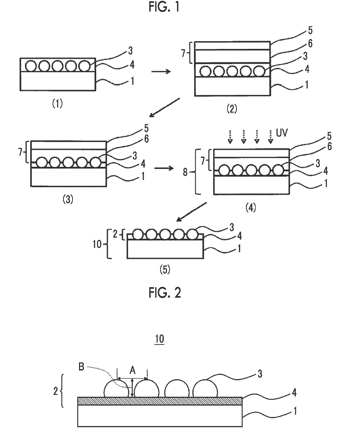
[0535]In the preparation of the protective films A to E, a pressure sensitive film was transferred to one surface of ZRT60 (manufactured by Fujifilm Corporation) instead of an antistatic and antifouling-treated polyethylene terephthalate (PET) film as the substrate for transferring a pressure sensitive sheet, so as to obtain protective films F to J having the lamination configuration of “ZRT60 / pressure sensitive adhesive layer / release film (PET film coated with silicone resin)”.
[0536]Maximum transmittance of the protective films F to J at wavelength of 250 nm to 300 nm in state (that is, a state of the pressure sensitive film) in which the release film was peeled was 70% to 74%.
[0537]In the antireflection films 9 to 13, the antireflection films 15 to 19 were obtained in the same manner, except that the protective films F to J were used instead of using the protective films A to E, the irradiation was performed on the surface coated with the layer (a) of the substrate with ultraviole...
example 3
[0539](Preparation of Composition for Forming Hard Coat Layer)
[0540]Each component was added in the following composition, and the obtained composition was introduced to a mixing tank, stirred, and filtrated with a polypropylene filter having a pore size 0.4 μm so as to obtain a hard coat layer coating liquid HC-2.
[0541](Hard Coat Layer Coating Liquid HC-2)
A-TMMT24.1parts by massAD-TMP11.8parts by massDPCA-6012.0parts by massIRGACURE 1272.1parts by massAS-16.9parts by massEthanol0.4parts by massMethanol6.7parts by mass1-Butanol4.8parts by massMethyl ethyl ketone (MEK)16.8parts by massMethyl acetate14.4parts by massFP-10.05parts by massAD-TMP: ditrimethylolpropane tetraacrylate (manufactured by Shin-Nakamura Chemical Co., Ltd., NK ESTER)DPCA-60: Polyfunctional acrylate oligomer containing caprolactone structure (manufactured by Nippon Kayaku Co., Ltd., KAYARAD)AS-1: A compound AS-1 corresponding the above patent document (A-6) was prepared in the same manner except that the reaction ...
PUM
| Property | Measurement | Unit |
|---|---|---|
| average primary particle diameter | aaaaa | aaaaa |
| surface free energy | aaaaa | aaaaa |
| contact angle | aaaaa | aaaaa |
Abstract
Description
Claims
Application Information
 - R&D
- Intellectual Property
- Life Sciences
- Materials
- Tech Scout
- Unparalleled Data Quality
- Higher Quality Content
- 60% Fewer Hallucinations
Browse by: Latest US Patents, China's latest patents, Technical Efficacy Thesaurus, Application Domain, Technology Topic, Popular Technical Reports.
© 2025 PatSnap. All rights reserved.Legal|Privacy policy|Modern Slavery Act Transparency Statement|Sitemap|About US| Contact US: help@patsnap.com


