Magnetic resonance imaging device, magnetic resonance imaging system, and parameter estimation method

a magnetic resonance imaging and parameter estimation technology, applied in the field of magnetic resonance imaging devices, can solve problems such as signal intensity changes, and achieve the effect of reducing the effect of magnetization transfer

Active Publication Date: 2019-07-25
HITACHI LTD
View PDF1 Cites 2 Cited by
  • Summary
  • Abstract
  • Description
  • Claims
  • Application Information

AI Technical Summary

Benefits of technology

[0016]According to the present invention, in imaging for obtaining a calculated image, a high frequency magnetic field pulse having a narrow frequency band that provides an excitation profile in which the excitation profile increases monotonously from one end to another end of the field of view is used. As a result, a signal of blood can be prevented from being attenuated from one end to another end of the field of view. Therefore, a change in T1 value depending on blood flow can be prevented, and a uniform T1 value can be calculated. In addition, by using the excitation pulse having a narrow frequency band, the magnetization transfer effect can be reduced. Therefore, the accuracy of T1 and T2 of brain parenchyma in a calculated image does not deteriorate.

Problems solved by technology

However, PTL 1 discloses the method in which a signal function is obtained even from an imaging pulse sequence, which is not analytically obtained, by numerical simulation to generate a calculated image.
In a case where a range having a given volume such as the head is imaged, blood flow moves in this volume, and thus there is a problem in that the signal intensity changes.

Method used


Image

  • Magnetic resonance imaging device, magnetic resonance imaging system, and parameter estimation method
  • Magnetic resonance imaging device, magnetic resonance imaging system, and parameter estimation method
  • Magnetic resonance imaging device, magnetic resonance imaging system, and parameter estimation method

Examples


first embodiment

[0035]Hereinafter, a first embodiment to which the present invention is applied will be described. Hereinafter, in all the diagrams for describing the embodiment of the present invention, components having the same functions are represented by the same reference numerals, and the description thereof will not be repeated.

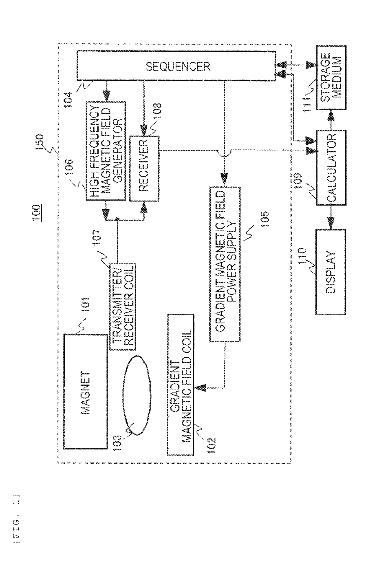
[0036]First, an overall configuration of an MRI device according to the embodiment will be described. FIG. 1 is a block diagram illustrating a schematic configuration of an MRI device 100 according to the embodiment. The MRI device 100 includes: a magnet 101 that generates a static magnetic field; a gradient magnetic field coil 102 that generates a gradient magnetic field; a sequencer 104; a gradient magnetic field power supply 105; a high frequency magnetic field generator 106; a transmitter / receiver coil 107 that irradiates a high frequency magnetic field and detects a nuclear magnetic resonance signal; a receiver 108; a calculator 109; a display 110; and a storage...

example 1

of RF Pulse

[0087]In this example, as the RF pulse (FIG. 5: 502) for excitation, only a main lobe (one peak) of a sinc function is used, and the application time is set as 2.4 ms. FIG. 9A illustrates the intensity and the phase. In addition, FIG. 9B illustrates an excitation profile 451 of the RF pulse.

[0088]Assuming that the application time is represented by t sec and the number of peaks is represented by n, a frequency band (full width at half maximum) of a sinc function is approximately represented by (n+1) / t Hz. Since the application time is 2.4 ms and the number of peaks is 1 in this excitation pulse, the frequency band (full width at half maximum) is 0.83 kHz. In a case where the frequency band is 1 kHz or lower, the magnetization transfer effect can be suppressed. Therefore, by using the excitation pulse of FIGS. 9A-9B, a subject parameter distribution can be obtained substantially without being affected by magnetization transfer.

[0089]In an excitation pulse of the related ar...

example 2

of RF Pulse

[0093]In this example, as the RF pulse (FIG. 5: 502) for excitation, a gaussian function is used. The application time is set as 4.8 ms. FIG. 11A illustrates the intensity and the phase. In addition, FIG. 11B illustrates a positional relationship between an excitation profile 452 of the RF pulse and a field of view 412.

[0094]Under the same application time, the frequency band of the excitation pulse having a gaussian function shape is about two times that of the sinc function having one peak. In FIG. 11B, the application time of the RF pulse is two times that of the sinc function of Example 1 (FIG. 9A). Therefore, the frequency band is about 0.8 kHz which is substantially the same as that of the RF pulse of FIG. 9A. Accordingly, even in a case where this excitation pulse is used, a subject parameter distribution can be obtained in a state where there is substantially no magnetization transfer effect.

[0095]In addition, as illustrated in FIG. 11B, a field of view in the z d...


PUM


Abstract

In a case where a subject parameter distribution is obtained using MRI, a magnetization transfer effect is suppressed such that the calculation accuracy of T1 and T2 of brain parenchyma can be improved and a variation in the T1 value of blood caused by the effect of blood flow can be reduced. In imaging for parameter estimation, a magnetization transfer effect is suppressed by using a high frequency magnetic field pulse having a narrow frequency band as an excitation pulse. In a case where the frequency band is narrow, the high frequency magnetic field pulse has a shape in which the excitation profile is similar to a Gaussian function. A rising portion of the shape is arranged in a field of view where the head is an imaging target.

Description

CROSS-REFERENCE TO RELATED APPLICATION[0001]The present application claims priority from Japanese application JP 2018-009813, filed on Jan. 24, 2018, the contents of which is hereby incorporated by reference into this application.TECHNICAL FIELD[0002]The present invention relates to a magnetic resonance imaging device and, in particular, relates to a technique of estimating a subject parameter by calculation.BACKGROUND ART[0003]A magnetic resonance imaging (MRI) device a medical image diagnostic device that obtains an image of a subject by causing nuclear magnetic resonance to occur in specific nuclei included in a tissue of a subject, typically, in hydrogen nuclei, receiving a nuclear magnetic resonance signal (echo signal) generated by the nuclear magnetic resonance, and reconstructing an image based on the received nuclear magnetic resonance signal.[0004]The intensity of the nuclear magnetic resonance signal obtained from the MRI device largely depends on the spin density of hydr...

Claims


Application Information

Patent Timeline
Patent Type & Authority Applications(United States)
IPC IPC(8): G01R33/36G01R33/56G01R33/385G06T11/00A61B5/055
CPCG01R33/3607G01R33/5608G01R33/385G06T11/006G06T11/008A61B5/055G06T2207/10088G01R33/4806G01R33/56G01R33/50G01R33/4833G01R33/4831
Inventor TANIGUCHI, YOAMEMIYA, TOMOKIYOKOSAWA, SUGURUSHIRAI, TORUOCHI, HISAAKI
Owner HITACHI LTD
Why Eureka
Try Eureka