Bone implant

Pending Publication Date: 2019-08-08
ATTENBOROUGH DENTAL LAB
View PDF1 Cites 8 Cited by
  • Summary
  • Abstract
  • Description
  • Claims
  • Application Information

AI Technical Summary

Benefits of technology

[0013]The at least one portion of the surface may be coated in a layer of adhesive. This allows the implant to be bonded to a body part in use.
[0014]The adhesive may be any dental, orthopaedic or other adhesive. Preferably the adhesive is cured by external input of a first energy. In order to get the first energy through to the adhesive, the implant preferably comprises at least one conduit whereby said first energy may be introduced into the adhesive. The at least one conduit extends through the body of the implant and opens at the at least one portion of the surface. This has the benefit of reducing the curing time from normal conventional adhesive methods. Examples of suitable energy include but are not limited to electromagnetic radiation, ultrasound or thermal energies. The first energy which travels through the conduit diverges at it leaves the conduit and contacts the adhesive, causing it to cure rapidly. Furthermore, in forming a layer of adhesive a proportion of the energy is internally reflected at the adhesive boundary. This leads to further diffusion away from the conduit opening. In order to be cured by the input of a first energy the adhesive may comprise an initiator which is responsive to the energy. In one embodiment, the adhesive is cured by application of UV light from a UV light source. In such an embodiment the initiator is a photoinitiator which is activated by the UV light. Using UV light as the energy source the adhesive may cure within 90 seconds. In another embodiment, the adhesive is cured by ultrasound energy from an ultrasound source. Ultrasound energy has the benefit that energy is only provided to the places where there are boundaries between materials, such as the bone adhesive boundary or the implant adhesive boundary. Thus, ultrasound energy provides for a very targeted form of energy which reduces curing time and is less damaging to the surrounding internal tissues. The adhesive may be selected from the group consisting of acrylate or methacrylate adhesives, dentine bonding agents, including but not limited to glass-ionomer composites, and bone cements. Typical adhesive components include cyanoacrylate, methyl-methacrylate, octyl-cyanoacrylate, N-butyl-cyanoacrylate, dimethacrylate and pentaerythritol triacrylate.
[0015]Preferably the implant comprises a flange extending around the periphery of the implant and protruding in a direction approximately at right angles away from the implant. When in use the flange will therefore protrude towards the body and away from the at least one portion of the surface. The flange provides a stand-off between the at least one portion of the surface and the body part, when the implant is in use. This means that the user can apply maximum pre

Problems solved by technology

However, using fixation screws for securing implants to bones is associated with several disadvantages.
Drill holes made for insertion of the screws weaken the bone's cortex and may result in further fracture in regions of thin cortical bone (e.g. osteoporotic bones, comminuted fracture fragments).
Anatomical structures that lie in close proximity to the deep cortex (e.g., nerves, vessels) may be injured while drilling the far cortex or when measuring pilot-hole depth for screw insertion.
Damage to the articular cartilage by screw protrusion into the joint may occur and is becoming more frequent with the increased prevalence of fixed angled locking implants.
Clinically, hardware failure and mal-union leads to persistent pain at the fracture site, reduced strength across the joint, restricted range of motion and cosmetic deformity, all of which have a major impact on patient life quality and could expose the patient to further operations.
Furthermore, actually positioning the implant in place and drilling into the bone requires invasive open surgery, which takes considerable time and greatly increases the potential for secondary bacterial infection.
Adhesives have been used in medical practice for many years but have only limited usage in the body.
For example they are not currently used in fra

Method used


Image

  • Bone implant
  • Bone implant
  • Bone implant

Examples


Example

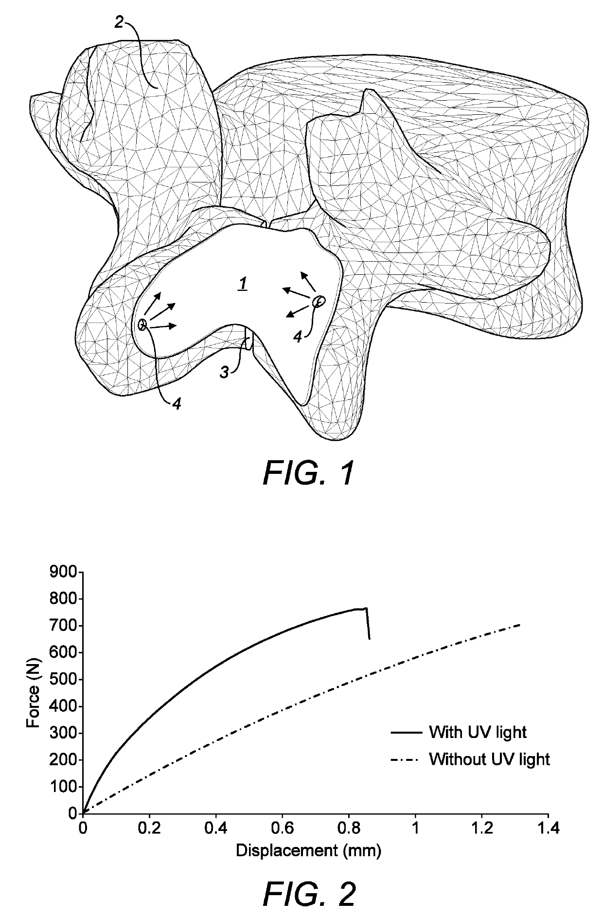
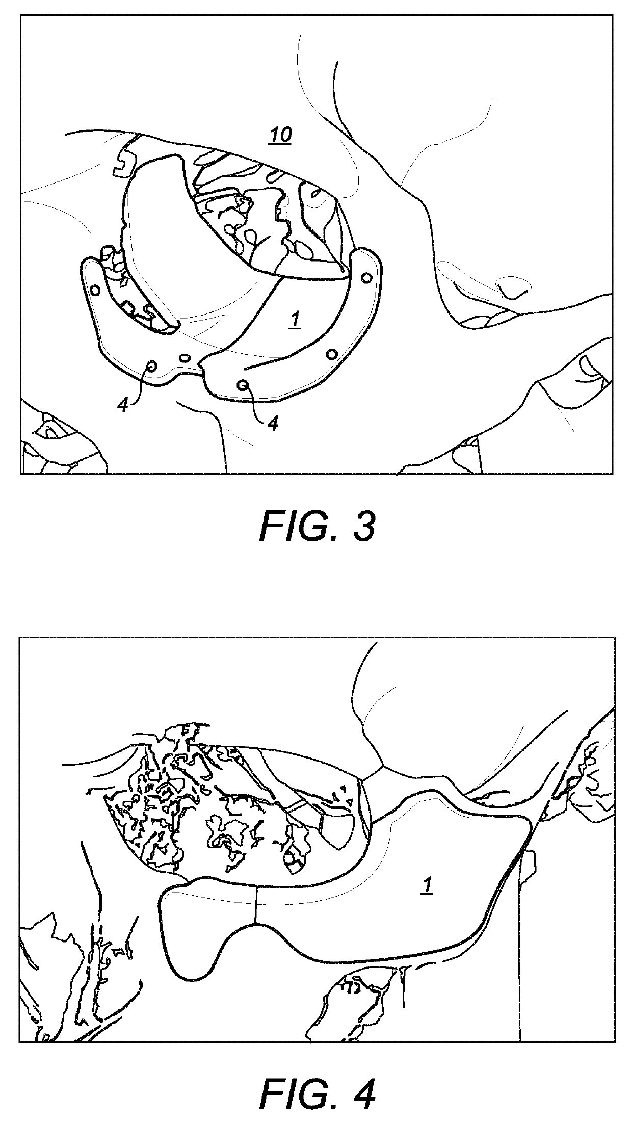
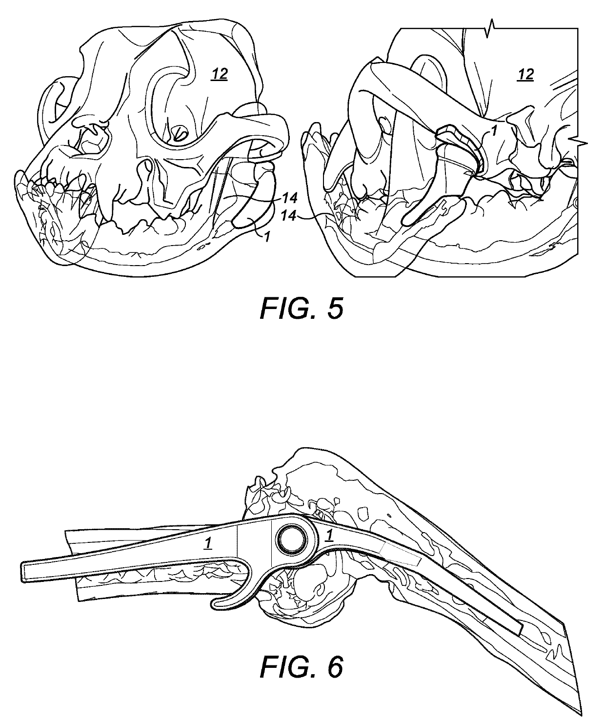
[0075]FIG. 1 shows an embodiment of the implant according to the invention. The implant is generally designated 1. The implant is shown attached to a human vertebra 2 which has a lamina defect 3 caused by a stress fracture in the bone. The defect in this case is malformation of the two halves of the vertebra so that there is no structural connection present. This can be a source of lower back pain. However having one of these conditions does not mean that back problems are a certainty. It does however present a higher risk compared to people that don't have the defect, towards developing pain. These conditions can cause mechanical pain, which is the kind of pain that come from within the moving parts of the spine. These conditions can also cause compressive pain, which is derived from pressure on the nerves in the lower back.

[0076]The implant 1 is custom made, which means that it is manufactured to specifically fit against the individual vertebra shown with the inside surface of the...


PUM

PropertyMeasurementUnit
Timeaaaaaaaaaa
Volumeaaaaaaaaaa
Volumeaaaaaaaaaa

Abstract

Disclosed herein is an implant for use in a body, at least one portion of the surface of the implant being mutually engageable with at least one portion of at least one body part.
Also disclosed is a method of surgery comprising the steps of: forming an implant comprising at least one portion of the surface of the implant being mutually engageable with at least one portion of at least one body part, applying a layer of adhesive to the at least one portion of the surface, and engaging the at least one portion of the surface with the at least one portion of at least one body part.

Description

FIELD OF THE INVENTION[0001]The present invention relates to an implant for use in the body and a method of surgery using said implant.BACKGROUND TO THE INVENTION[0002]In cases of injury, disease or trauma it is common for body parts to be supported in some form or other. Typical supports range from metal implants to venous tubes and the indications that require support range from broken legs, to tumour invasion damage to venous embolism. Supporting implants in most cases are physically retained in position, either by stitching or gluing. Orthopaedic implants are commonly fastened in place using screws or bolts of various different designs.[0003]Fracture fixation is one of the most common procedures in orthopaedic surgery. Osteosynthesis by plating and fixation screws is commonly the favoured technique, especially when absolute stability of the fracture site is required (e.g., intra-articular fractures). However, using fixation screws for securing implants to bones is associated wit...

Claims


Application Information

Patent Timeline
IPC IPC(8): A61B17/00A61F2/30
CPCA61B17/00491A61F2/30749A61F2/30942A61F2/44A61F2/2875A61F2/2803A61B17/70A61F2002/2878A61F2002/2882A61F2002/30948A61F2002/30943A61B2017/00951A61B2017/005A61F2/28A61F2/2846A61F2/30A61F2002/2821A61F2002/2825A61F2002/285A61F2002/30784A61F2002/30003A61F2002/4631A61L31/022A61L31/10A61L31/14A61L2430/02A61L31/06C08L71/12A61B17/84A61L24/00A61B2034/108A61B34/10A61B2034/105A61F2002/30955G16H50/50A61B2034/102
Inventor ATTENBOROUGH, EDWARD JOHN
Owner ATTENBOROUGH DENTAL LAB
Why Eureka
Try Eureka