
Systes and methods for controlling bladder irrigation

a technology applied in the field of systes and methods for controlling bladder irrigation, can solve the problems of acute problems such as urinary retention, acute bladder overdistention, and inability to perform complete hemostasis such as applying, and achieve the effect of saving time and effort for medical professionals and reducing the concern about additional operations on patients

Inactive Publication Date: 2019-08-29
SEOUL NAT UNIV HOSPITAL
View PDF0 Cites 3 Cited by
  • Summary
  • Abstract
  • Description
  • Claims
  • Application Information

AI Technical Summary

Benefits of technology

The patent describes a system that automatically notifies medical professionals when there is a problem with supplying or collecting fluid needed for bladder irrigation. The system accurately determines when to replace the fluid supply and / or collector, which reduces the need for individual replacement even when multiple supplies or collectors are provided, saving time and effort for medical professionals. Overall, the system improves the efficiency and convenience of bladder irrigation procedures.

Problems solved by technology

Partially because of the surgical bed of the transurethral surgery being constantly in contact with fluid such as urine in the bladder and partially because of the nature of the surgical site, it is difficult to perform complete hemostasis such as applying pressure on the site.
Even though a surgeon tries his best to perform meticulous coagulation on the surgical bed after resection of the tissue, some degree of oozing causing hematuria from the surgical bed is inevitable.
If these blood clots interfere with urinary drainage a urethral catheter, acute problems such as bladder overdistention, urinary retention, or ensuing severe abdominal discomfort may occur.
If the color of hematuria in the draining tube is severe, the possibility of formation of blood clots is high, and the inflow rate of the sterile irrigating fluid needs to be increased.
However, the conventional continuous bladder irrigation has the following problems.
Considering that there is a considerable number of patients having the transurethral surgery every day, to perform monitoring the color of hematuria and replacing the fluid supplies / collectors requires a considerable amount of manpower.
In addition, the tasks may be physically demanding for a female nurse.
Considering the weight of the conventional fluid supply / collector and the number of replacements, the task may be a hard work for a female nurse.
Second, the replacement timing of the irrigation fluid supply or the fluid collector cannot be accurately determined.
If the inflow fluid supply or the fluid collector is not replaced at the right time, the continuous bladder irrigation may stop, significantly increasing the possibility of blood clot formation.
If blood clot blocks the catheter due to inappropriate management in the supply / drainage of the irrigating fluid, the medical professionals may immediately need to disconnect the tubing system and then have to irrigate the bladder manually with normal saline commonly using syringe.
These events may cause significant inconvenience to both the patient and the medical professional.
Moreover, manual irrigation may break the closed system of the irrigation channels, which may cause bacterial contamination of the urinary tract of the patient.

Method used


Image

  • Systes and methods for controlling bladder irrigation
  • Systes and methods for controlling bladder irrigation
  • Systes and methods for controlling bladder irrigation

Examples


first embodiment

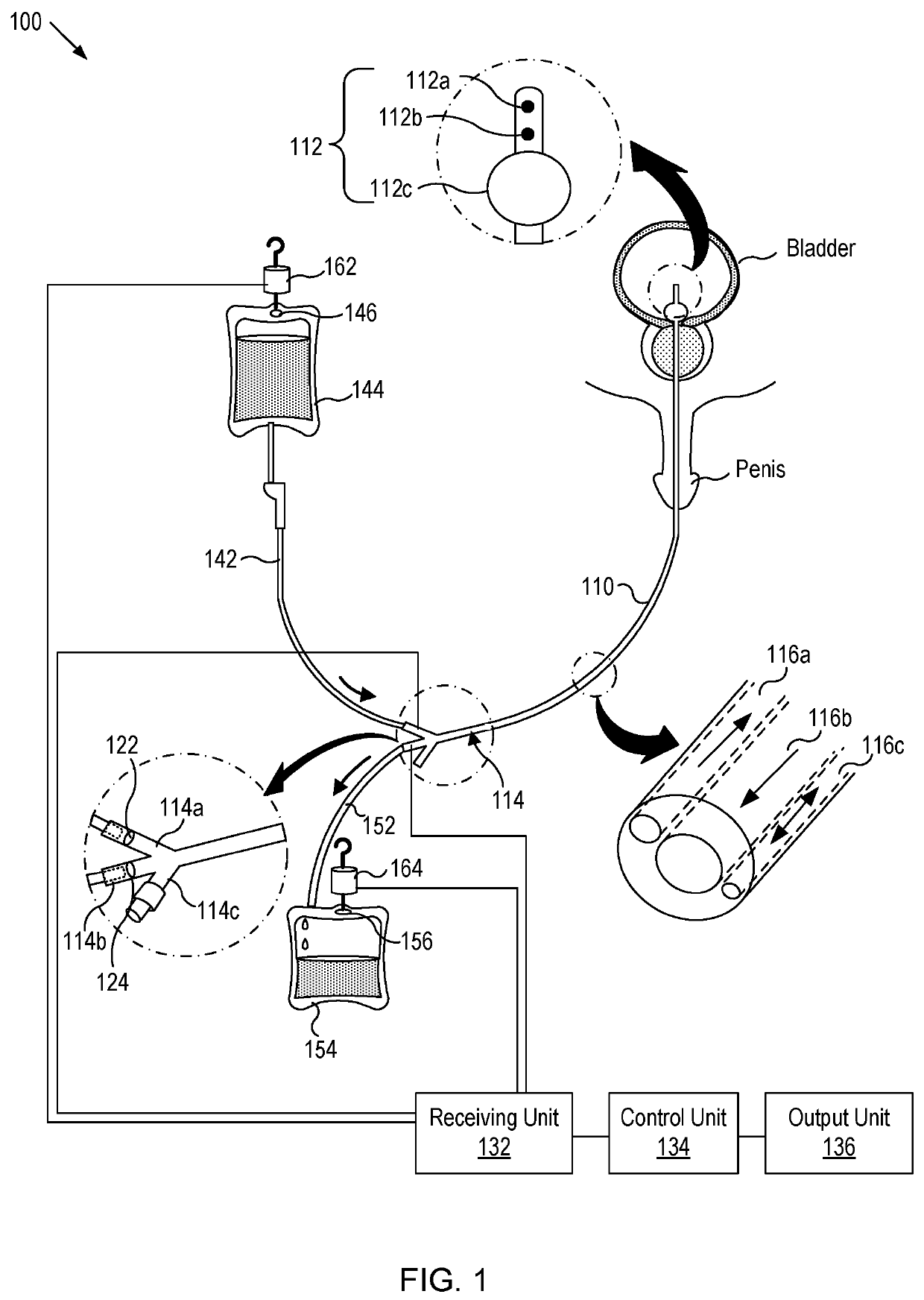
[0038]FIG. 1 shows a schematic diagram of a control system according to the first embodiment of the present disclosure. As depicted, the continuous bladder irrigation control system (or shortly control system) 100 includes a three-way urethral catheter 110, flow speed sensors 122 and 124, a receiving unit 132, a control unit 134 and an output unit 136.

[0039]In embodiments, the three-way urethral catheter 110 has a total of three lumens or passageways in its catheter design. It includes an inside tip portion 112 and a port portion 114. The inside tip portion 112 is a portion to be inserted into the bladder through the urethra of the patient. The port portion 114 includes an inflow funnel serving for a first port 114a through which a fluid is supplied into the bladder, a drainage funnel serving for a second port 114b through which the fluid in the bladder is drained from the bladder, and a balloon funnel serving for a third port 114c for inflating the balloon 112c at the inside tip of...

second embodiment

[0072]FIG. 4 shows a schematic diagram of a control system 200 according to the second embodiment of the present disclosure. As depicted, the continuous bladder irrigation control system (or shortly control system) 200 includes a catheter 110, a flow regulator 142, a pressure sensor 222, a color sensor 224, a receiving unit 232, a control unit 234 and an output unit 236. In the following sections, the description of the elements common to both the control systems 100 and 200 will not be repeated since the common elements have the similar structure and functions in both systems.

[0073]The pressure sensor 222 measures the internal pressure of the bladder and located near the first port 114a of the catheter 110. In alternative embodiments, the pressure sensor 222 may be located in the first fluid line 142 between the fluid supply 144 and the first port 114a. The pressure sensor 222 may be based on (but not limited to) mechanical, electrical, or semiconductor technology.

[0074]FIG. 5 show...

third embodiment

[0098]FIG. 8 shows a schematic diagram of a control system (or shortly control system) 300 according to a third embodiment of the present disclosure. As depicted, the control system 300 includes valves 310a, 310b, a receiving unit 332, a control unit 334, and an output unit 336. In the following sections, the description of the elements common to both the control systems 100 and 300 will not be repeated since the common elements have the similar structure and functions in both systems.

[0099]The control system 300 includes a plurality of inflow fluid supplies (or, shortly fluid supplies) 144a, 144b and a plurality of fluid collectors 154a, 154b. The control system 300 further includes a plurality of weight sensors 162a, 162b for measuring the weights of the plurality of fluid supplies 144a, 144b, respectively, and a plurality of weight sensors 164a, 164b for measuring the weights of the plurality of fluid collectors 154a, 154b, respectively.

[0100]The plurality of fluid supplies 144a,...


PUM


Abstract

The present invention relates to systems and methods for controlling flow through the urinary bladder and, more specifically, systems and methods for controlling continuous bladder irrigation after surgical treatment of lower urinary tract disorders. The control system for continuous bladder irrigation includes a catheter having a first port though which a first fluid enters a bladder and a second port through a second fluid exits the bladder; a first flow speed sensor for measuring a first speed of the first fluid; a second flow speed sensor for measuring a second speed of the second fluid; a control unit for sending, based on the first and second speeds, a warning signal of an abnormality in infusing the first fluid into the bladder and in draining the second fluid from the bladder.

Description

CROSS-REFERENCE TO PRIOR APPLICATIONS[0001]This application claims priority of Korean Patent Application No. 10-2018-0024183, filed on Feb. 28, 2018, which is all hereby incorporated by reference in its entirety.TECHNICAL FIELD[0002]The present invention relates to systems and methods for controlling flow through the urinary bladder and, more specifically, systems and methods for controlling continuous bladder irrigation after surgical treatment for lower urinary tract disorders.DESCRIPTION OF THE RELATED ART[0003]In general, to treat lower urinary tract disorders, such as bladder and prostate diseases, a medical professional may insert an indwelling urethral catheter after surgery. These types of surgery are diverse, including open prostatectomy, transurethral resection of bladder tumor, transurethral resection of prostate, or various transurethral laser prostate surgery for benign prostatic hyperplasia, such as potassiumtitanyl-phosphate (KTP) laser prostatectomy, or holmium laser...

Claims


Application Information

Patent Timeline
IPC IPC(8): A61M3/02
CPCA61M3/0283A61M3/0295A61M2025/0037A61M2025/1061A61M2210/1085A61M2205/3334A61M2205/3344A61M2205/3393A61M2205/18A61M3/0208A61M3/0212A61M3/0216A61M3/022A61M3/0287A61M3/0241A61M1/77A61M31/00A61B5/205A61M1/777
Inventor OH, SEUNG-JUNEKONG, HYOUN-JOONG
Owner SEOUL NAT UNIV HOSPITAL
Learn More