Optical feedback-based repetitive frequency adjustable optical frequency comb

a technology feedback, which is applied in the direction of instruments, laser details, active medium shape and construction, etc., can solve the problems of uneasy control of the number of carriers, poor flatness and uncertain carrier space, and the number of optical frequency comb generated by such methods is relatively large, and achieves the effect of simple tunable frequency space and effective solution

Active Publication Date: 2019-10-10
SOUTH CHINA UNIV OF TECH
View PDF0 Cites 16 Cited by
  • Summary
  • Abstract
  • Description
  • Claims
  • Application Information

AI Technical Summary

Benefits of technology

[0015]Compared with the prior art, the present invention has following advantages and technical effects:
[0016]A pump light output by the single-mode semiconductor pump light source pumps the single-frequency optical fiber laser resonant cavity through the wavelength division multiplexer, and after a laser signal which is output from the optical fiber resonant cavity through the wavelength division multiplexer goes through the optical circulator, the laser signal enters the first optical fiber coupler to achieve laser beam splitting. A part of the light, through the laser frequency modulation device and the tunable laser-delay module, enters the optical circulator for being injected in the single-frequency optical fiber laser resonant cavity again to achieve an optical feedback, while another part of the light enters the other second optical fiber coupler, and part of the light which is output from the second optical fiber coupler enters the photoelectric detector for being converted into an electrical signal. Such electrical signal carries information of amplitude and frequency fluctuations of the laser. After the electrical signal and a signal of the highly-stable signal source are operated and processed by the error signal processing system, they are loaded on the laser frequency modulation device to achieve laser frequency lock, and a laser frequency comb is generated. Compared with the conventional solution of generating an optical frequency comb based on a mode-locked laser or an optical microcavity, the present invention combines the optical feedback and the frequency lock, and provides an effective solution which is simpler with tunable frequency space.

Problems solved by technology

Advantages of this solution lie in simple structure and a large number of carriers generated, but defects, such as uneasy control of the number of carriers, poor flatness and uncertain carrier space, still exist.
The optical frequency comb generated by such method has a relatively large number, but has defects such as poor carrier flatness and uncontrollable number of the carrier.
This solution possesses advantages such as stable wavelet space, simple generating method and the like, but a high radio frequency drive voltage is needed if a large number of carriers are to be obtained, while the carrier flatness is unsatisfactory.
This method possesses advantages like a relatively large number of the generated optical frequency combs and good flatness, but such method possesses disadvantages such as unapparent carrier phase relationships, strong carrier noise and the like.

Method used


Image

  • Optical feedback-based repetitive frequency adjustable optical frequency comb

Examples


embodiment 1

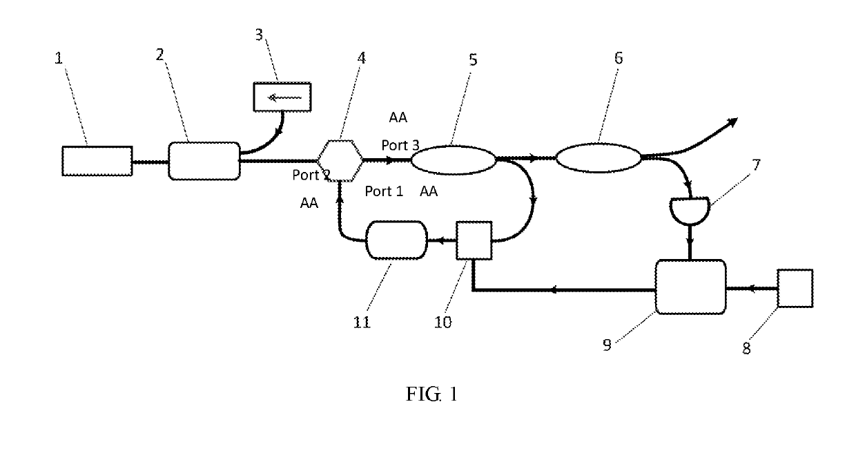
[0020]In the present embodiment, a 980 nm single-mode semiconductor laser serving as a single-mode semiconductor pump light source 3, backward pump performed on a single-frequency laser resonant cavity 1 was achieved through a 980 / 1550 nm polarization-maintaining wavelength division multiplexer 2. The single-frequency laser resonant cavity 1 was a single-frequency optical fiber DBR (Distributed Bragg Reflector) resonant cavity having an output laser wavelength of 1550.52 nm. After going through a 1550 nm polarization-maintaining optical fiber circulator 4, the output laser entered a first optical fiber coupler 5 having a splitting ratio of 50:50. A highly-stable signal source 8 in the embodiment was a highly-stable temperature-compensation crystal oscillator having a frequency of 50 MHz, a laser frequency modulation device 10 was an acoustic optical modulator, and a tunable laser-delay module 11 was an optical fiber delay line in 1 km length. A part of the light which was output fro...


PUM

PropertyMeasurementUnit
repetition frequencyaaaaaaaaaa
output laser wavelengthaaaaaaaaaa
frequencyaaaaaaaaaa

Abstract

The present invention provides a repetition frequency-tunable optical frequency comb generated by basis of optical feedback. The optical frequency comb comprises a single-frequency laser resonant cavity, a wavelength division multiplexer, a single-mode semiconductor pump light source, an optical circulator, a first optical fiber coupler, a second optical fiber coupler, a photoelectric detector, a highly-stable signal source, an error signal processing system, a laser frequency modulation device and a tunable laser-delay module. The present invention performs delay-time processing to the single-frequency laser by the tunable laser-delay module, and achieves an optical feedback by the optical circulator for injecting to the resonant cavity, generating a series of tunable laser longitudinal modes with equal frequency space. Meanwhile, in combination with the highly-stable signal source, the error signal processing system and the laser frequency modulation device, a laser frequency lock is achieved, and the laser frequency comb is generated. The invention obtains a repetition frequency-tunable laser frequency comb with a simple and practical method, having an extensive application prospect and huge application value in fields such as optical fiber sensing and spectroscopy of atom and molecule.

Description

TECHNICAL FIELD[0001]The present invention relates to an optical frequency comb, and particularly relates to a repetition frequency-tunable optical frequency comb generated by basis of optical feedback.BACKGROUND OF THE PRESENT INVENTION[0002]Optical frequency comb, being a light source which has a comb-like frequency spectrum, possesses significant applications in the related fields such as high-precision frequency standard, precise distance measurement, microwave photonic arbitrary waveform generator, microwave photonic signal processing, dense wavelength division multiplexing, and the like, and the precision of an atomic clock can be enhanced by two orders and above based on an optical clock of the optical comb. In view of its important theoretical significance and application value, the optical comb has become a hotspot studied in the related field.[0003]There are several conventional solutions for generating the optical comb: the first is that using an output in time domain of ...

Claims


Application Information

Patent Timeline
Patent Type & Authority Applications(United States)
IPC IPC(8): G02F1/11H01S3/067H01S3/094
CPCG02F1/113G02F2201/02H01S3/094003G02F2201/58G02F2203/25H01S3/0675H01S3/094065H01S3/067H01S3/06791H01S3/0912H01S3/0933H01S3/1106H01S3/1068H01S3/1109H01S3/10092H01S3/10046H01S3/082
Inventor XU, SHANHUIZHAO, QILAIYANG, ZHONGMINFENG, ZHOUMINGYANG, CHANGSHENG
Owner SOUTH CHINA UNIV OF TECH
Why Eureka
Try Eureka