Transcatheter Heart Valve with Plication Window and Tissue Anchors

a transcatheter heart valve and tissue anchor technology, applied in the field of transcatheter delivery prosthetic valves, can solve the problems of paravalvular leakage around an implanted replacement valve, enlarged heart, and loss of elasticity and efficiency, and achieve the effect of improving the quality of life and reducing the risk of complications

Active Publication Date: 2019-12-26
VDYNE INC
View PDF0 Cites 48 Cited by
  • Summary
  • Abstract
  • Description
  • Claims
  • Application Information

AI Technical Summary

Benefits of technology

[0049]FIG. 17 is an illustration of a perspective view of a heart valve prosthesis according to the present invention having a upper cuff with three uncovered plication windows and a central aperture having the collapsible flow control sleeve (FCS) disposed therein and providing an axial tube valve.

Problems solved by technology

Diseased or damaged valves, which can be congenital, age-related, drug-induced, or caused by infection, can result in an enlarged, thickened heart that loses elasticity and efficiency.
While these prosthetic valves offer minimally invasive methods for heart valve repair and / or replacement, challenges remain to provide prosthetic valves that prevent leakage between the implanted prosthetic valve and the surrounding tissue (paravalvular leakage) and for preventing movement and / or migration of the prosthetic valve that could occur during the cardiac cycle.
For example, the repair or replacement of a valve can present numerous challenges due to differing anatomies and etiologies presented by individual patients, including varying sizes and topologies associated with an abnormal or unhealthy aortic valve that prevents proper alignment of the replacement (e.g., prosthetic) valve which can cause leakage, valve impingement or dislodgement of the prosthesis.
Additionally, stenosis of a valve can deform the valvular area which can result in paravalvular leakage around an implanted replacement valve.
However, one downside of this design was that it could only be placed in the descending aorta instead of the heart itself.
For this reason it did not fully correct the valve problem, only alleviate the symptoms.
However, the struts of these valves tended to fracture from fatigue over time.
However, a downside of this design is that it allows some regurgitation.
Additionally, a problem with stent-style replacement valves is that they often continue to have the regurgitation or leakage problems of prior generations of valves, as well as require expensive materials engineering in order to cope with the 100's of millions of cycles encountered during just a few years of normal heart function.

Method used


Image

  • Transcatheter Heart Valve with Plication Window and Tissue Anchors
  • Transcatheter Heart Valve with Plication Window and Tissue Anchors
  • Transcatheter Heart Valve with Plication Window and Tissue Anchors

Examples


example —

[0126]Example—General

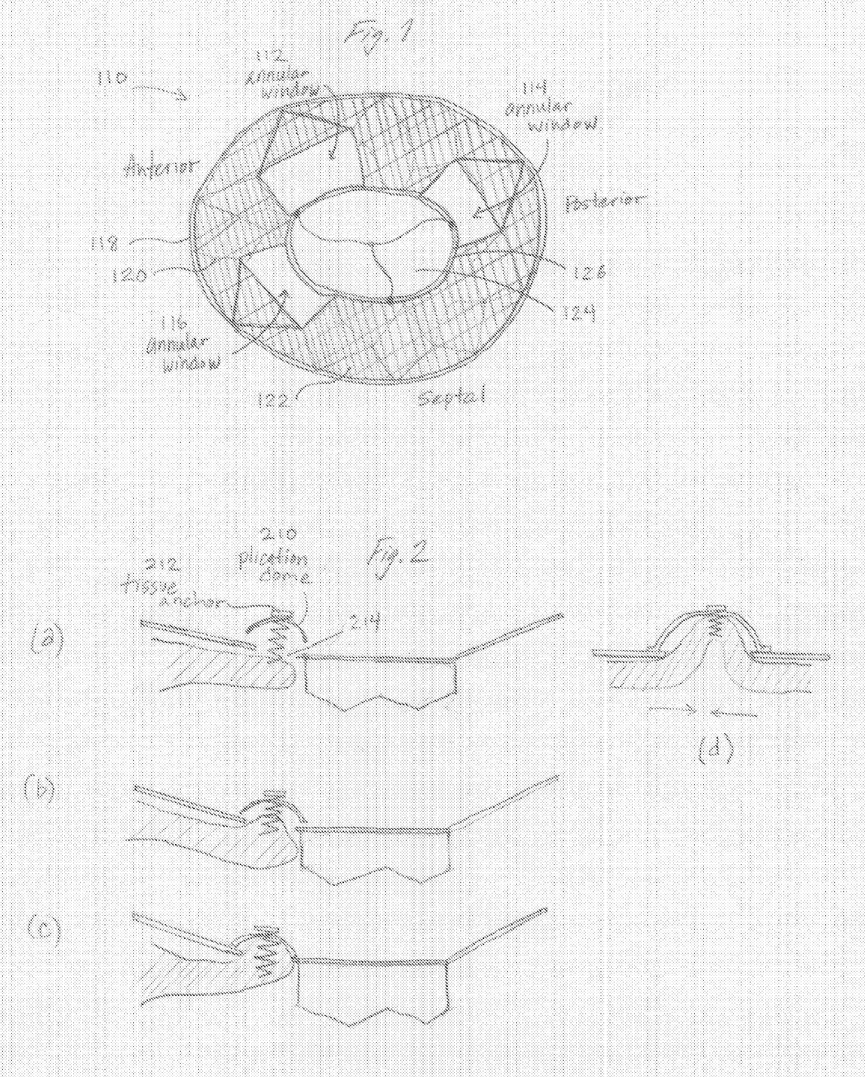
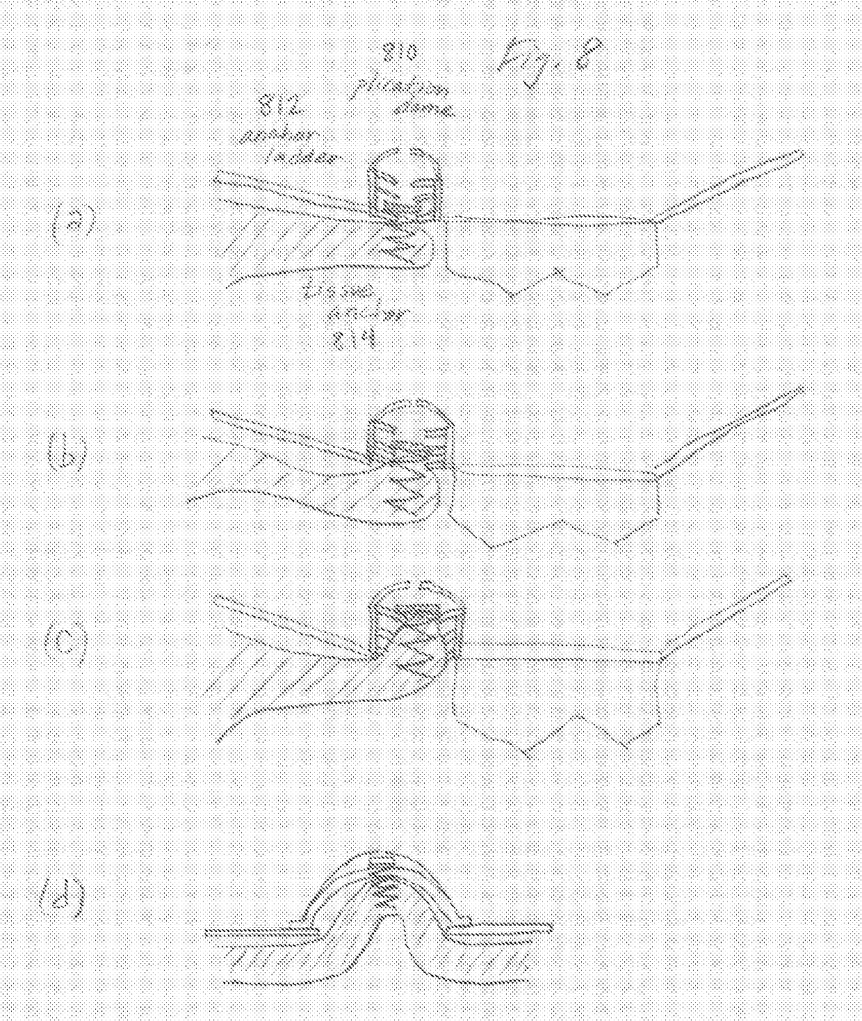
[0127]Provided herein are systems, devices and methods suitable for percutaneous delivery and implantation of a prosthetic heart valve having a reciprocating pressure conduit valve in a heart of a patient. In some embodiments, methods and devices are presented for the treatment of valve disease by minimally invasive implantation of artificial or prosthetic heart valves. For example, a prosthetic heart valve device, in accordance with embodiments described herein, can be implanted for replacement of a diseased or damaged native valve or prior implanted prosthetic valve in a patient, such as in a patient suffering from valve stenosis. In further embodiments, the device is suitable for implantation and replacement of other diseased or damaged heart valves, including the tricuspid, pulmonary, aortic, and mitral heart valves.

[0128]In this example, a heart valve prosthesis in a radially expanded or deployed configuration (e.g., a deployed state) includes a frame or ex...

example — threaded

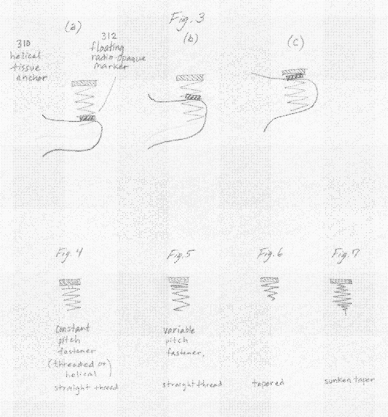
[0145]Example—Threaded

[0146]In another preferred embodiment of a transcatheter valve, there is provided a feature wherein the atrial frame comprises a threaded structure, wherein the threaded structure allows for a simple circular screw-type deployment of the device into a native annulus to aid in sealing and sizing of the top collar into the native annulus.

[0147]Example—Method

[0148]In a preferred embodiment of the invention, there is also provided a method of controlling flow of bodily fluid within an enclosed cavity of a human body, said enclosed cavity having a reciprocating pressure differential, the method comprising the steps: (i) delivering the transcatheter prosthetic medical device described herein, to the enclosed cavity within the human body; (ii) arranging the prosthetic medical device whereby the sleeve and sleeve channel are arranged parallel to a flow of fluid entering the enclosed cavity; (iii) expanding a top frame above an entrance to the enclosed cavity to mount t...

example

[0149]Delivery Example

[0150]The transcatheter prosthetic heart valve may be percutaneously delivered using a transcatheter process via the carotid, but both carotid, femoral, sub-xyphoid, and intercostal access across the chest wall. The device is delivered via catheter to the right or left atrium and is expanded from a compressed shape that fits with the internal diameter of the catheter lumen. The compressed pinch valve is loaded external to the patient into the delivery catheter, and is then pushed out of the catheter when the capsule arrives to the atrium. The cardiac treatment technician visualizes this delivery using available imaging techniques such as fluoroscopy or ultrasound, and in a preferred embodiment the pinch valve self-expands upon release from the catheter since it is constructed in part from shape-memory material, such as Nitinol®, a nickel-titanium alloy used in biomedical implants.

[0151]In another embodiment, the pinch valve may be constructed of materials that ...


PUM


Abstract

The invention relates to a transcatheter heart valve replacement (A61F2/2412), and in particular a device and method for percutaneous annular plication and heart valve deployment for mounting a pressure actuated flow control sleeve, a pinch valve, as a replacement device for a heart valve, whereby the prosthesis has an atrial annular flange or cuff having one or more integral plication windows connected to a pressure actuated flow control sleeve extending into the ventricle, wherein the is a reciprocating mechanical member that is compressed by pressurized working fluid within the heart during ventricular systole.

Description

CROSS-REFERENCE TO RELATED APPLICATIONS[0001]Provided by Application Data Sheet per USPTO rules.STATEMENT REGARDING FEDERALLY SPONSORED R&D[0002]Provided by Application Data Sheet per with USPTO rules.NAMES OF PARTIES TO JOINT RESEARCH AGREEMENT[0003]Provided by Application Data Sheet per with USPTO rules.REFERENCE TO SEQUENCE LISTING[0004]Provided by Application Data Sheet per USPTO rules.STATEMENT RE PRIOR DISCLOSURES[0005]Provided by Application Data Sheet per USPTO rules.BACKGROUND OF THE INVENTIONField of the Invention[0006]The invention relates to a transcatheter heart valve replacement (A61F2 / 2412), and in particular a device and method for percutaneous annular plication and heart valve deployment for mounting a pressure actuated flow control sleeve, a pinch valve, as a replacement device for a heart valve, whereby the prosthesis has an atrial annular flange or cuff having one or more integral plication windows connected to a pressure actuated flow control sleeve extending in...

Claims


Application Information

Patent Timeline
Patent Type & Authority Applications(United States)
IPC IPC(8): A61F2/24
CPCA61F2210/0014A61F2220/0016A61F2230/0019A61F2220/0008A61F2230/001A61F2230/0017A61F2250/0067A61F2250/0098A61F2/2427A61F2/2418A61F2/2412A61F2250/0069
Inventor VIDLUND, ROBERTCHRISTIANSON, MARKHOLTAN, DAVIDVIDLUND, CAMERON
Owner VDYNE INC
Why Eureka
Try Eureka