
Conversion of waste plastic to propylene and cumene

a technology of cumene and waste plastic, which is applied in the field of conversion of waste plastic to propylene and cumene, can solve the problems of high cost of cumene produced from intermediates derived from petroleum feedstocks and affecting the economics of the bisphenol a production process

Active Publication Date: 2020-01-16
SABIC GLOBAL TECH BV
View PDF0 Cites 13 Cited by
  • Summary
  • Abstract
  • Description
  • Claims
  • Application Information

AI Technical Summary

Benefits of technology

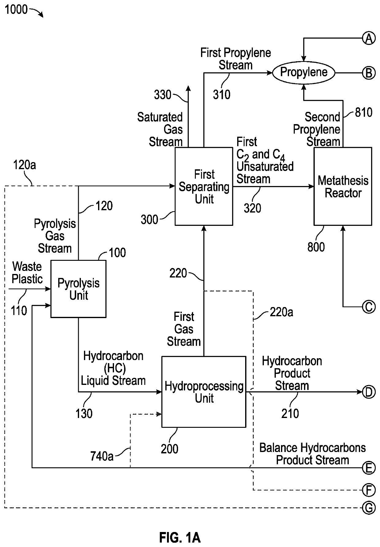
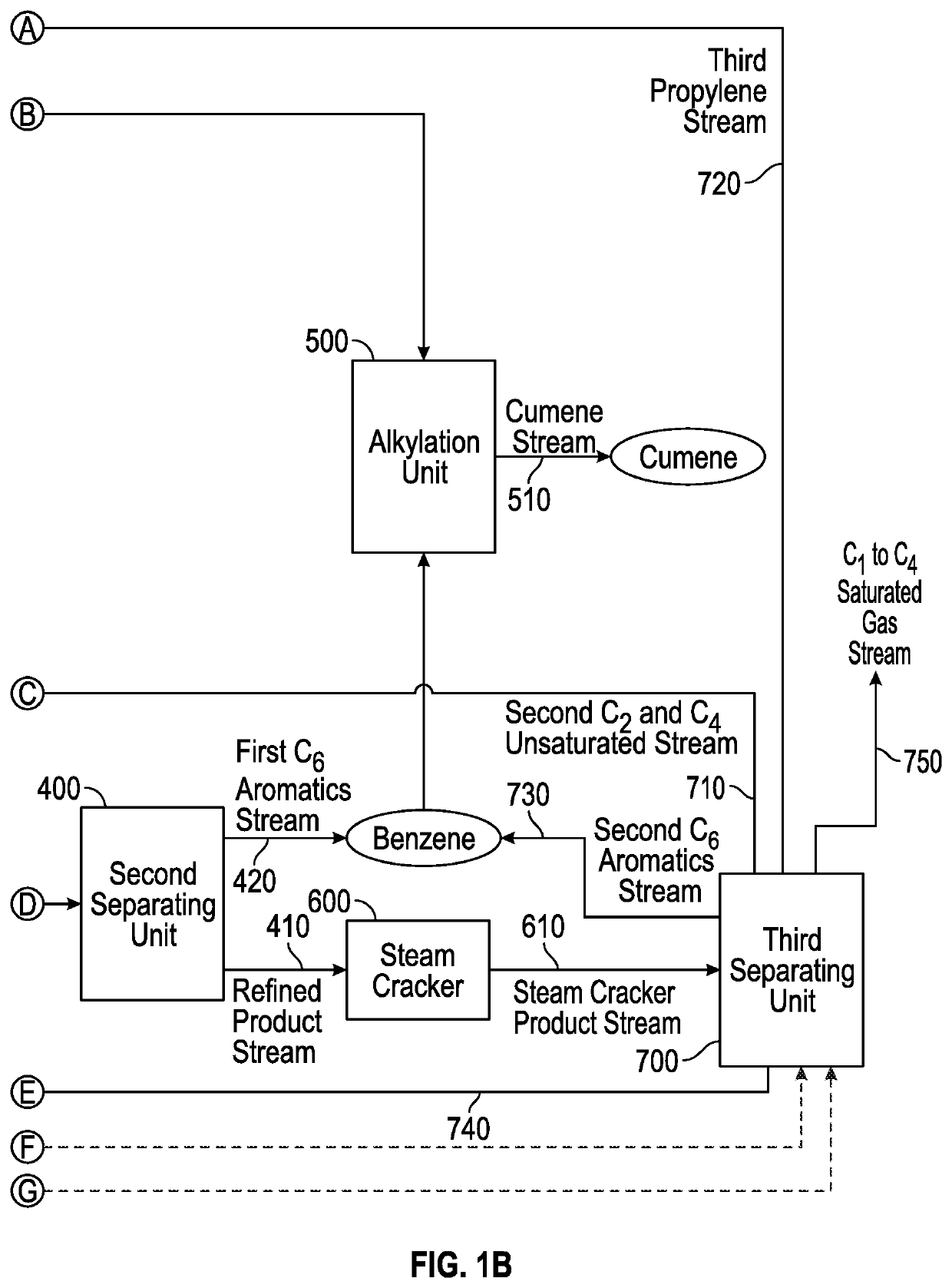
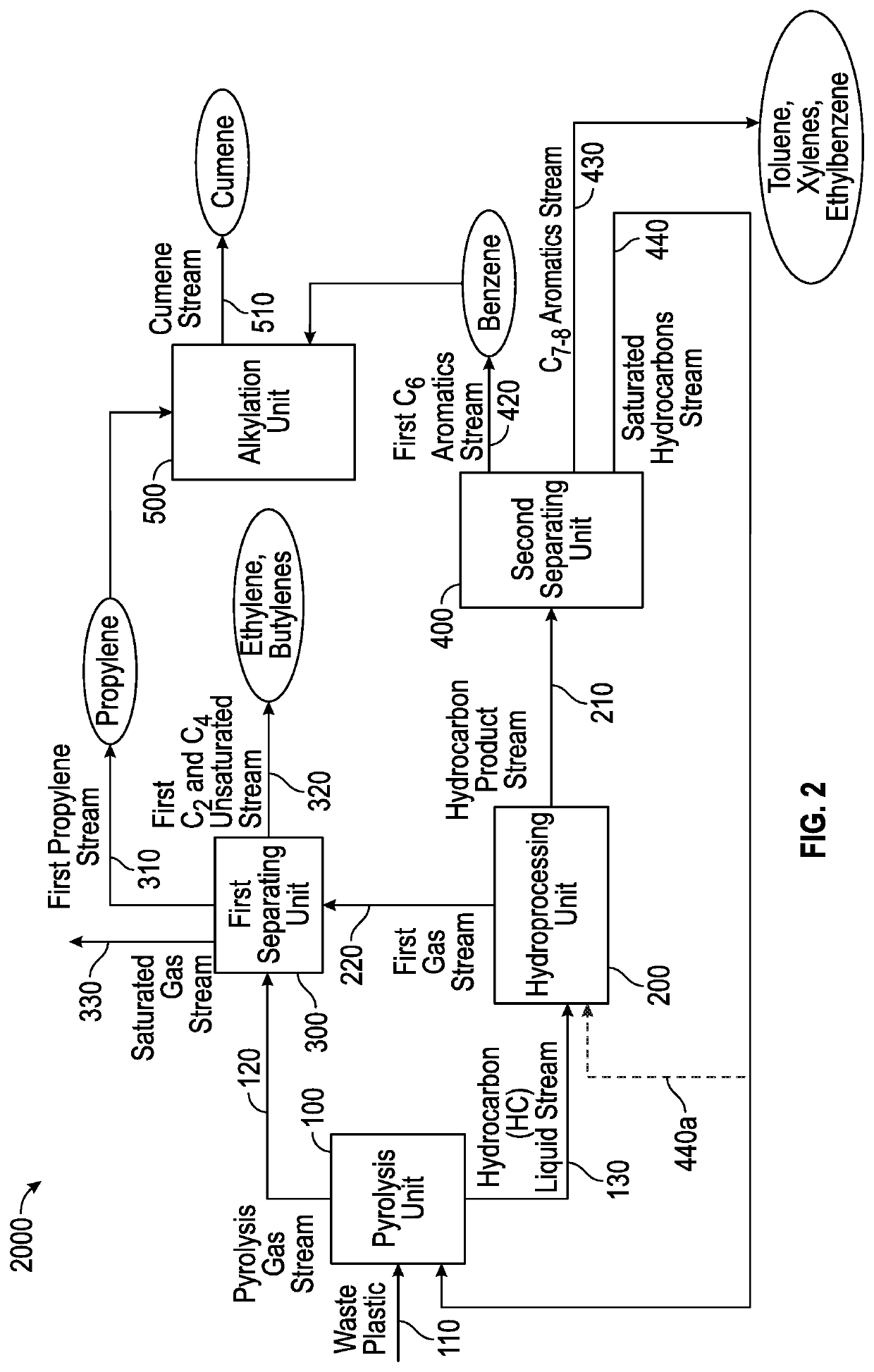
The patent describes a process for producing propylene and cumene using plastic waste. The process involves converting plastic waste to a hydrocarbon liquid and a pyrolysis gas stream through a pyrolysis unit. The hydrocarbon liquid is then contacted with a hydroprocessing catalyst in the presence of hydrogen to produce a hydrocarbon product and a first gas stream. The first gas stream is then separated to produce a first propylene stream, a first C2 and C4 unsaturated stream, a saturated gas stream, and a balance hydrocarbon product. The first C6 aromatics stream is then introduced to a first separating unit to produce a second C6 aromatics stream, a second C2 and C4 unsaturated stream, a saturated gas stream, and a balance hydrocarbon product. The second C6 aromatics stream and the second C2 and C4 unsaturated stream are then combined to produce a second propylene stream. The second C6 aromatics stream and the first C7-8 aromatics stream are then introduced to an alkylation unit to produce cumene. The process produces a high yield of propylene and cumene from plastic waste.

Problems solved by technology

The cumene produced from intermediates derived from petroleum feedstock is expensive, and as a result impacts the economics of the bisphenol A production process.

Method used


Image

  • Conversion of waste plastic to propylene and cumene
  • Conversion of waste plastic to propylene and cumene
  • Conversion of waste plastic to propylene and cumene

Examples


example 1

[0096]High severity pyrolysis of mixed waste plastic was conducted to investigate the production of propylene and benzene for cumene synthesis. The mixed waste plastic had 82% olefinic feed (e.g., high-density polyethylene (HDPE), low-density polyethylene (LDPE), linear low-density polyethylene (LLDPE), and polypropylene (PP)); 11% polystyrene (PS); and the remaining 7% was polyethylene terephthalate (PET). The pyrolysis was conducted in continuous catalytic cracking in circulating fluidized bed. The cracking was done with 57.5% spent fluid catalytic cracking (FCC) catalyst and with 42.5% ZSM-5 based zeolite additive and operated between 390-560° C. cup mix temperature of feed and catalyst. The feed rate of the plastic feed was 316 g / hr and the catalyst / feed weight ratio was about 30. In the case of a single stage pyrolysis process, the propylene content of the pyrolysis effluent was 23.7%, as it can be seen from the data in Table 1. The overall yield of light gas olefins was about ...

example 2

[0100]Low severity pyrolysis of mixed waste plastic was conducted to investigate the production of propylene and benzene for cumene synthesis. The mixed waste plastic had 82% olefinic feed (e.g., high-density polyethylene (HDPE), low-density polyethylene (LDPE), linear low-density polyethylene (LLDPE), and polypropylene (PP)); 11% polystyrene (PS); and the remaining 7% was polyethylene terephthalate (PET). The mixed plastic waste was pyrolyzed as described in Example 1, except for the temperature, which was about 450° C. A pyrolysis effluent was further hydrotreated to saturate all the liquid olefins, and then was further sent to steam cracking. A hydrotreated pyrolysis liquid can typically comprise 35-45% paraffins, 35-45% iso-paraffins, 15-20% naphthenes, and 5-10% aromatics, wherein the hydrotreated pyrolysis liquid boils below 400° C. The hydrotreated pyrolysis liquid could be subjected to (i) steam cracking alone; (ii) steam cracking followed by catalytic cracking with C4-C5 cr...

example 3

[0101]A mixed plastic waste was cracked in modular units at low severity conditions; or catalytically cracked in a circulating fluidized bed at high severity; or catalytically cracked in a circulating fluidized bed at low severity to produce a pyrolysis oil. The results from these cracking experiments are shown below. The cup mix temperature was varied between 400-600° C., specifically 450-550° C. Depending on the severity of the operation, the gases and the liquid products were separated. The composition of the cracked liquid product is shown below in the tables. The saturated hydrocarbons present in the gas were sent to gas crackers which were an ethane cracker or propane cracker. The gas cracker was selected depending on the desired end product. The cracked liquid from the pyrolysis unit was sent to hydrotreating to saturate all the liquid olefins, as this is a requirement for the liquid / naphtha cracker. Hydrotreating was performed at 300-450° C. and at a pressure of 20-100 barg ...


PUM

PropertyMeasurementUnit
Temperatureaaaaaaaaaa

Abstract

A process for producing propylene and cumene comprising converting plastics to hydrocarbon liquid and pyrolysis gas in pyrolyzer; feeding hydrocarbon liquid to hydroprocessor to yield hydrocarbon product and first gas stream; introducing hydrocarbon product to second separator to produce first C6 aromatics and refined product; feeding refined product to steam cracker to produce steam cracker product; introducing steam cracker product to third separator to produce second C6 aromatics, third propylene stream, second C2&C4 unsaturated stream, C1-4 saturated gas, and balance hydrocarbons product; introducing pyrolysis gas and / or first gas stream to first separator to produce first propylene stream, first C2&C4 unsaturated stream, and saturated gas stream; feeding first and / or second C2&C4 unsaturated stream to metathesis reactor to produce second propylene stream; feeding first and / or second C6 aromatics, and first, second, and / or third propylene stream to alkylation unit to produce cumene; and conveying balance hydrocarbons product to pyrolyzer and / or hydroprocessor.

Description

TECHNICAL FIELD[0001]This disclosure relates to the production of high value products, such as olefins and aromatic hydrocarbons from mixed plastics via processes which include pyrolysis, hydroprocessing, steam cracking, alkylation, and olefin metathesis, wherein cumene and propylene are the preferred products.BACKGROUND[0002]Cumene is an important chemical intermediate, with almost all produced cumene being converted to cumene hydroperoxide, which is an intermediate in the synthesis of other industrially important chemicals, such as phenol and acetone, which can be further used in the production of bisphenol A. Current processes for producing cumene convert petroleum feedstock to benzene and propylene, which are then reacted to form cumene. The cumene produced from intermediates derived from petroleum feedstock is expensive, and as a result impacts the economics of the bisphenol A production process. Thus, there is an ongoing need to develop methods for producing cumene from feedst...

Claims


Application Information

Patent Timeline
IPC IPC(8): C10G1/00C10G1/10C10G1/02C10G69/06C07C2/66C07C6/04
CPCC10G1/02C10G2300/1003C10G2400/20C10G1/002C10G1/10C10G69/06C07C2/66C07C6/04C10G2400/30C10G47/04C10G47/12C10G47/14C10G69/123C07C11/06C07C15/085
Inventor RAMAMURTHY, KRISHNA KUMARNARAYANASWAMY, RAVICHANDERGANAPATHY BHOTLA, VENKATA RAMANARAYANANSTANISLAUS, ALEXANDERGANJI, SANTOSH
Owner SABIC GLOBAL TECH BV
Learn More