Method for Inkjet Printing an Organic-Inorganic Perovskite
Active Publication Date: 2020-01-23
AALTO UNIVERSITY FOUDATION SR +2
View PDF0 Cites 2 Cited by
Summary
Abstract
Description
Claims
Application Information
AI Technical Summary
This helps you quickly interpret patents by identifying the three key elements:
Problems solved by technology
Method used
Benefits of technology
[0141]An advantage of the present invention is that precise amounts of precursor ink can be deposited, and that such amount can be distributed regularly over the surface that is to be covered, in particular the active surface of the solar cell.
[0142]In an embodiment, the method of the invention comprises depositing 5-50 μl, preferably 10-40 μl, more preferably 15-30 μl even more preferably 20-27 μl and most preferably 21-26 μl per cm2. These amounts are preferably deposited with respect to one (1) cm2 of the active surface of the perovskite solar cell.
[0143]Thanks to the stability of the perovskite ink of the invention, the method of the invention allows for depositing comparatively larges surfaces of perovskites, preferably in a continuous manner. Laboratory perovskite solar cells, typically have a surface of 1 cm2. The present invention encompasses printing perovskite ink on surfaces larger than 1 cm2, preferably larger than 10 cm2, more preferably larger than 50 cm2. In an embodiment, the method of the invention encompasses printing perovskite layers on surfaces of 90 cm2100 cm2 or larger. Indeed, the occurrence of stable ink in accordance with the invention allows depositing perovskite layers by printing on surfaces of 200 cm2 or larger, 300 cm2 or larger 400 cm2 or larger 500 cm2 or larger, and even surfaces of sizes in the dm2 or m2 range. Such surfaces can be deposited in continuous, non-interrupted deposition processes, where printing nozzles operate continuously for covering the desired surface. It is noted that such surfaces may enc
Problems solved by technology
Like dye sensitized solar cells (DSSCs), these solution processed photovoltaic systems could also be fabricated via mass reproducible printing schemes, which may further reduce their overall production cost.
However, the traditional PSCs configurations have not been found stable and exhibited poor stability in long term aging tests.
Although claimed as fully printable mesoscopic perovskite solar cell in earlier reports, the two steps of fabrication (i.e. spray pyrolysis and manual infiltration of perovskite precursor solution) for carbon based PSCs cannot be realized as ‘printing steps’ and may also generate performance variations in the fabricated devices.
However, after almost 5-7 years of progress in PSCs research, the reports on inkjet printing of the perovskite precursor inks are a few (references 25-27) due to limitations such as the rapid transformation of perovskite crystals from the liq
Method used
Image
Click on the blue label to locate the original text in one second.
Reading with bidirectional positioning of images and text.
Examples
example 1
ls in Accordance with an Embodiment of the Invention
1. Preparation of Solar Cells for Deposition of Precursor Solution
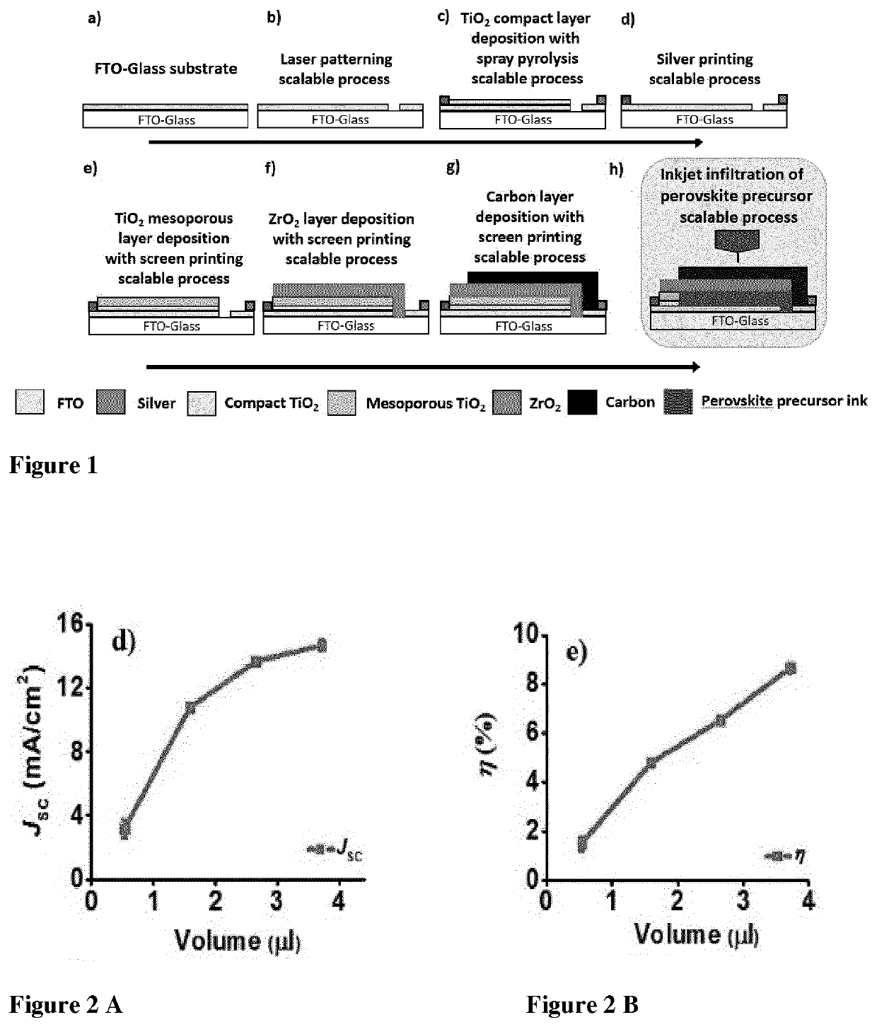
[0185]Triple layer solar cells of the configuration TiO2 / ZrO2 / C, deposited on a conducing transparent substrate but yet lacking a perovskite light harvester were prepared as follows.
[0186]Fluorine doped tin oxide (FTO) coated glass substrates (10×10 cm2, RSH=7 Ω / Sq, Product code: TCO22-7, Solaronix) were first etched with an automated fiber laser, and cleaned by sequential sonications in Hellmanex 1% aqueous solution, acetone, and isopropanol (15 min each). Then a compact layer of TiO2 (30-40 nm) was deposited by spray pyrolysis over the etched glass substrates placed on a hot-plate set to 550° C., of a diluted solution of titanium diisopropoxide bis(acetylacetonate) (75% in isopropanol, Sigma-Aldrich) in absolute ethanol (1:80) using oxygen as a carrier gas. Areas of the substrate had been masked with glass strips to prevent the coating in the subsequent silver area...
example 2
n of Stability of Inks of the Invention and Prior Art Inks
experiment 1
[0198]Two inks were compared for demonstrating the superior stability at room temperature of the ink according to an embodiment of the invention.
Compositions of Inks
[0199]Ink 1: 1.1 g PbI2, 0.38 g MAI, 0.029 g AVAI (40 wt % in GBL, γ-butyrolactone)
[0200]Ink 2: 1.1 g PbI2, 0.38 g MAI (No AVAI).
[0201]Ink 2 contains equimolar concentrations of PbI2 and MAI (methylammonium iodide). Ink 1 contains, in addition 5-AVAI, which is a compound of formula (I) in accordance with an embodiment of the invention.
[0202]In the photographs in FIG. 11, panels a) and b), it is apparent that both inks provide clear solutions when the inks are fresh. After storage at room temperature (25° C.) for 20 minutes, ink 2 shows clouding indicating precipitation, as shown in panel c) of FIG. 11 and in FIG. 12.
[0203]In conclusion, Ink 1 produced in accordance with an embodiment of the invention showed remarkable stability compared to Ink 2. Ink 1 is particularly suitable for inkjet infiltration, whereas ink 2 will ...
PUM
Abstract
The present invention provides a method for depositing an organic-inorganic perovskite, the method comprising the step of depositing a perovskite precursor solution comprising one or more organic cation, wherein said precursor solution preferably deposited by inkjet printing. The method is particularly useful in the manufacture of perovskite solar cells. For depositing the perovskite, a perovskite precursor solution or ink is preferably used, which comprises an organic cation carrying an anchoring group, such as 5-ammonium valeric acid. Surprisingly, the presence of the latter compound renders the precursor solutions stable and suitable for inkjet printing.
Description
TECHNICAL FIELD[0001]The present invention relates to a method for depositing at least part of an organic-inorganic perovskite, a method for producing a perovskite solar cell and perovskite solar cells obtainable by the method of the invention.PRIOR ART AND THE PROBLEM UNDERLYING THE INVENTION[0002]Perovskite solar cells (PSCs) have stunned the photovoltaic community with an incredible progress in recent years while showing conversion efficiencies more than 22%. Like dye sensitized solar cells (DSSCs), these solution processed photovoltaic systems could also be fabricated via mass reproducible printing schemes, which may further reduce their overall production cost. However, the traditional PSCs configurations have not been found stable and exhibited poor stability in long term aging tests. Alternative strategies, for instance, introducing Al2O3 either as buffer layer to prevent ion migration from metal electrode, replacing mesoporous TiO2 with Al2O3 to suppress the UV instability o...
Claims
Application Information
Patent Timeline
Application Date:The date an application was filed.
Publication Date:The date a patent or application was officially published.
First Publication Date:The earliest publication date of a patent with the same application number.
Issue Date:Publication date of the patent grant document.
PCT Entry Date:The Entry date of PCT National Phase.
Estimated Expiry Date:The statutory expiry date of a patent right according to the Patent Law, and it is the longest term of protection that the patent right can achieve without the termination of the patent right due to other reasons(Term extension factor has been taken into account ).
Invalid Date:Actual expiry date is based on effective date or publication date of legal transaction data of invalid patent.