Battery box for electric vehicles

a battery box and electric vehicle technology, applied in the field of battery boxes, can solve the problems of reducing the resistance of the frame, the loss of space for the battery box casing, and the inability to absorb crash energy, so as to improve the assembly of the bottom part, improve the volume of the battery box, and satisfy flatness

Active Publication Date: 2020-04-30
CONSTELLIUM SINGEN
View PDF0 Cites 2 Cited by
  • Summary
  • Abstract
  • Description
  • Claims
  • Application Information

AI Technical Summary

Benefits of technology

[0024]It is then possible to obtain a satisfying flatness by having a small degree of deformation with bending because of the big radii at the chamber while having the smallest inner radii on the upper and lower parts of the bend extruded aluminum element to optimize the volume of the battery box.
[0025]This configuration improves the assembly of the bottom part to the peripheral frame, as it permits to obtain a better flatness of the lower surface of the peripheral frame. It ensures a better tightness between the peripheral frame and the bottom part after sealing.

Problems solved by technology

Unless, if a lower or higher angle is obtained, typically less than 85° or higher than 95°, it induces a loss of space for the casing of battery boxes.
This solution encounters some issue, in particular welding distortion, which is detrimental to the sealing of the peripheral frame to the bottom and / or the top plate.
Another disadvantage is the presence of a heat affected zone induced by the operation of welding which reduces the resistance of the frame and its ability to absorb crash energy.
But it remains detrimental to sealing due to non-flat areas on the upper and lower side of the corner due to the bending deformation.
Additionally due to the presence of a deformed area at the corner, it is not possible to fix with rivets the top cover in this area due to the lack of space to drill holes and sealing may remain difficult to achieve.

Method used


Image

  • Battery box for electric vehicles
  • Battery box for electric vehicles
  • Battery box for electric vehicles

Examples


Embodiment Construction

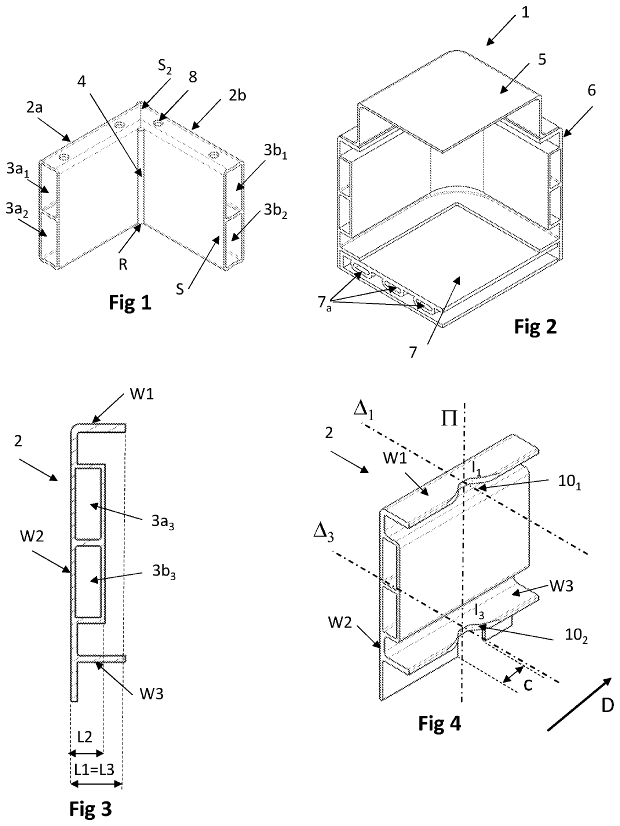
[0063]FIG. 1 represents a part of a frame of a battery box according to the prior art constituted of two extruded elements 2a, 2b assembled by welding. Elements 2a and 2b are two similar extruded elements each with two hollow chambers 3a1, 3a2, 3b1, 3b2, presenting a global section S perpendicular to the extrusion direction. Elements 2a and 2b are positioned each other at 90° via a surface S2. The surface S2 is obtained by cutting at 45° an extremity of each element 2a and 2b; the angle of 45° being defined with regards to the extrusion longitudinal direction. The two elements 2a and 2b rests to the surface S2 and form an angle substantially at 90°; the angle of 90° being defined as the angle formed by the extrusion direction of the two elements 2a and 2b. Finally, they are assembled by welding, typically arc welding or laser welding. A weld seam 4 is positioned at the corner of the two elements 1a and 1b. The frame is drilled at different positions to allow the fixture of a cover (...


PUM

PropertyMeasurementUnit
angleaaaaaaaaaa
angleaaaaaaaaaa
angleaaaaaaaaaa

Abstract

A battery box for electric or hybrid motor vehicles, comprising a peripheral frame which has a generally convex polygonal shape, a bottom part and a top cover; the bottom part being joined to a lower surface of the peripheral frame, said peripheral frame comprising at least an aluminum extruded element, bent in a single direction in at least a position along the extrusion longitudinal direction according an angle wherein said bent aluminum extruded element at the said position presents at least two different inner radii of curvatures.

Description

FIELD OF THE INVENTION[0001]The present invention concerns the field of electric or hybrid motor vehicles.[0002]The present invention concerns more particularly battery boxes of such an electric or hybrid motor vehicle, consisting of a peripheral frame which has a generally convex polygonal shape in planar view, a bottom part which is joined to the lower surface of the peripheral frame made of aluminum alloy and a top cover for closing.STATE OF THE ART[0003]A battery box may comprise a chamber receiving electrical energy storage cell element units, enabling production of electrical energy for driving the electric or hybrid vehicle. The units of electrical energy storage cell elements are placed in the battery box, after which the battery box is mounted in an electric or hybrid motor vehicle.[0004]An electric motor vehicle or hybrid vehicle (vehicle which is provided with an internal combustion engine) requires a large number of batteries for driving a motor. Some examples of battery...

Claims


Application Information

Patent Timeline
Patent Type & Authority Applications(United States)
IPC IPC(8): B60L50/64B60L50/15H01M2/10B60K1/04B21D11/08H01M50/224H01M50/271
CPCH01M2/1083B60L50/64B60K1/04B21D11/08B60L50/15B21D7/00B21D7/06H01M50/224H01M50/271Y02E60/10
Inventor SCHWARZ, KAIKUTSCHER, MATTHIASWIEDEMANN, JOCHENMANNHERZ, JAKOBSCHMID, THOMAS
Owner CONSTELLIUM SINGEN
Why Eureka
Try Eureka