Fiber microphone

Active Publication Date: 2020-05-21
THE RES FOUND OF STATE UNIV OF NEW YORK
View PDF0 Cites 2 Cited by
  • Summary
  • Abstract
  • Description
  • Claims
  • Application Information

AI Technical Summary

Benefits of technology

[0044]This technology has the potential of providing a number of important advantages over existing technology. The microphone could be made without any active electronic components, saving cost and power. A directional output can be obtained that is nearly independent of the frequency of the sound. A directional output can be obtained that does not require a significant port spacing (approximately 1 cm on current hearing aids). This could greatly simplify hearing aid design and reduce cost.
[0045]It is therefore an obje

Problems solved by technology

This comes with the cost o

Method used


Image

  • Fiber microphone
  • Fiber microphone
  • Fiber microphone

Examples


example 1

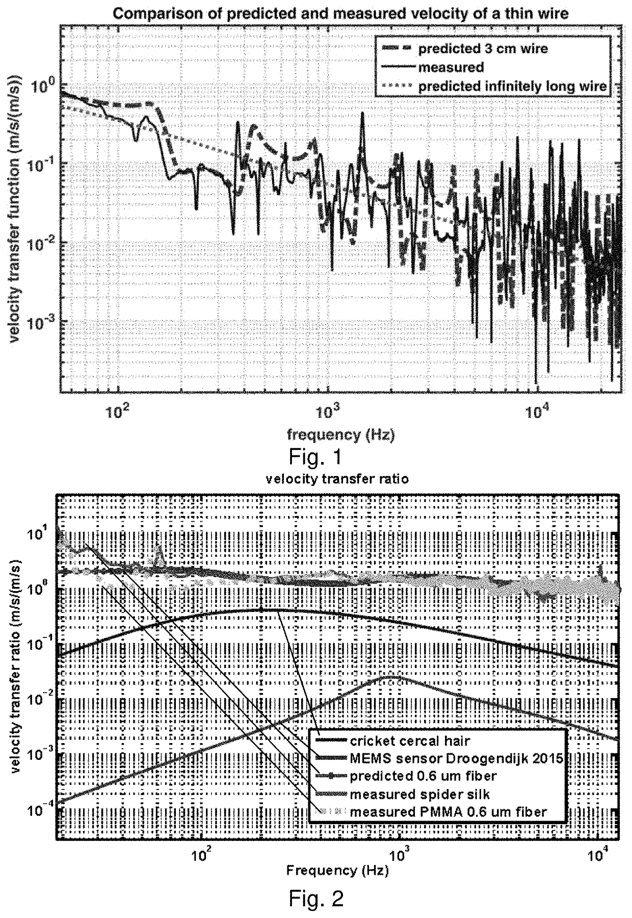
[0178]In order to verify the results of the analytical model for an acoustic sensor, measurements were obtained of the response of a thin wire due to a plane wave sound field. Stainless steel fiber having a diameter of 6 μm was obtained from Blue Barn Fiber (Hayden, Id.) [72]. This is intended to be spun into yarn for clothing. The fiber is in the form of continuous strands having a length of several centimeters.

[0179]A single strand of stainless steel fiber was soldered to two wires spanning a distance of 3 cm. The fiber was not straight, in this experiment, which may influence the ability to accurately predict its sound-induced motion. The fiber was placed in an anechoic chamber and subjected to broad-band sound covering the audible range of frequencies. The sound pressure was measured in the vicinity of the wire using a B&K 4138 ⅛th inch reference microphone. The sound source was 3 meters from the wire which resulted in a plane sound wave at frequencies above approximately 100 Hz...

example 2

[0210]In some applications, an infrasonic sensor is desired, with a frequency response fl that extends to an arbitrarily low frequency, such as a tenth of hundredth of a Hertz. Such a sensor might be useful for detecting fluid flows associated with movement of objects, acoustic impulses, and the like. Such an application works according to the same principles as the sonic sensor applications, though the length of individual runs of fibers might have to be greater.

[0211]In addition, the voltage response of the electrode output to movements is proportional to the velocity of the fiber, and therefore one would typically expect that the velocity of movement of fluid particles at infrasonic frequencies would low, leading to low output voltages. However, in some applications, the fluid movement is macroscopic, and therefore velocities may be appreciable. For example, in wake detection applications, the amplitude may be quite robust.

[0212]Generally, low frequency sound is detected by senso...

example 3

[0216]To intuitively illustrate the transverse motion of spider silk due to fluctuating airflow in the direction perpendicular to its long axis, sound is recorded from the silk motion. The complex airborne acoustic signal used here contains low frequency (100 Hz-700 Hz) wing beat of insects and high frequency (2 kHz-10 kHz) song of birds. Spider dragline silk with diameter d=500 nm was collected from a female spiderling Araneus diadematus (body length of the spider is about 3 mm). A strand of spider silk (length L=8 mm) is supported at its two ends slackly, and placed perpendicularly to the flow field. The airflow field is prepared by playing sound using loudspeakers. A plane sound wave is generated at the location of the spider silk by placing the loudspeakers far away (3 meters) from the silk in our anechoic chamber. The silk motion is measured using a laser vibrometer (Polytec OFV-534).

[0217]While the geometric forms (cob-web, orb-web, and single strand), size and tension of the ...


PUM


Abstract

A microphone, comprising at least two electrodes, spaced apart, configured to have a magnetic field within a space between the at least two electrodes; a conductive fiber, suspended between the at least two electrodes; in an air or fluid space subject to waves; wherein the conductive fiber has a radius and length such that a movement of at least a central portion of the conductive fiber approximates an oscillating movement of air or fluid surrounding the conductive fiber along an axis normal to the conductive fiber. An electrical signal is produced between two of the at least two electrodes, due to a movement of the conductive fiber within a magnetic field, due to viscous drag of the moving air or fluid surrounding the conductive fiber. The microphone may have a noise floor of less than 69 dBA using an amplifier having an input noise of 10 nV/√Hz.

Description

CROSS REFERENCE TO RELATED APPLICATIONS[0001]The present application is a non-provisional of, and claims benefit of priority from U.S. Provisional Patent Application No. 62 / 432,046, filed Dec. 9, 2016, the entirety of which is expressly incorporated herein by reference.FIELD OF THE INVENTION[0002]The present invention relates to the field of fiber microphones which respond to acoustic waves by a viscous drag process.BACKGROUND OF THE INVENTION[0003]Miniaturized flow sensing with high spatial and temporal resolution is crucial for numerous applications, such as high-resolution flow mapping [73], controlled microfluidic systems [74], unmanned micro aerial vehicles [75-77], boundary layer flow measurement [78], low-frequency sound source localization [79], and directional hearing aids [37]. It has important socio-economic impacts involved with defense and civilian tasks, biomedical and healthcare, energy saving and noise reduction of aircraft, natural and man-made hazard monitoring and...

Claims


Application Information

Patent Timeline
IPC IPC(8): H04R9/02G10L25/18H04R9/08H04R29/00
CPCH04R9/08H04R9/025H04R2307/025H04R2307/029H04R2307/027G10L25/18H04R29/004H04R1/08H04R1/406H04R3/005H04R5/027H04R9/02H04R2201/401H04R2430/20H04R2499/11H04S2400/15H04R9/048
Inventor MILES, RONALD N.ZHOU, JIAN
Owner THE RES FOUND OF STATE UNIV OF NEW YORK
Why Eureka
Try Eureka