

Catalyst composite and method for manufacturing the same
a catalyst and composite technology, applied in the field of catalyst composites, can solve the problems of limited commercialization in terms of large-scale air-breathing electrodes, limited use of catalysts for catalysts, and limited preservation of pt-based materials, so as to enhance the economic feasibility of hydrogen production, excellent catalyst activity, and excellent performance and durability
- Summary
- Abstract
- Description
- Claims
- Application Information
AI Technical Summary
Benefits of technology
Problems solved by technology
Method used
Image

Examples
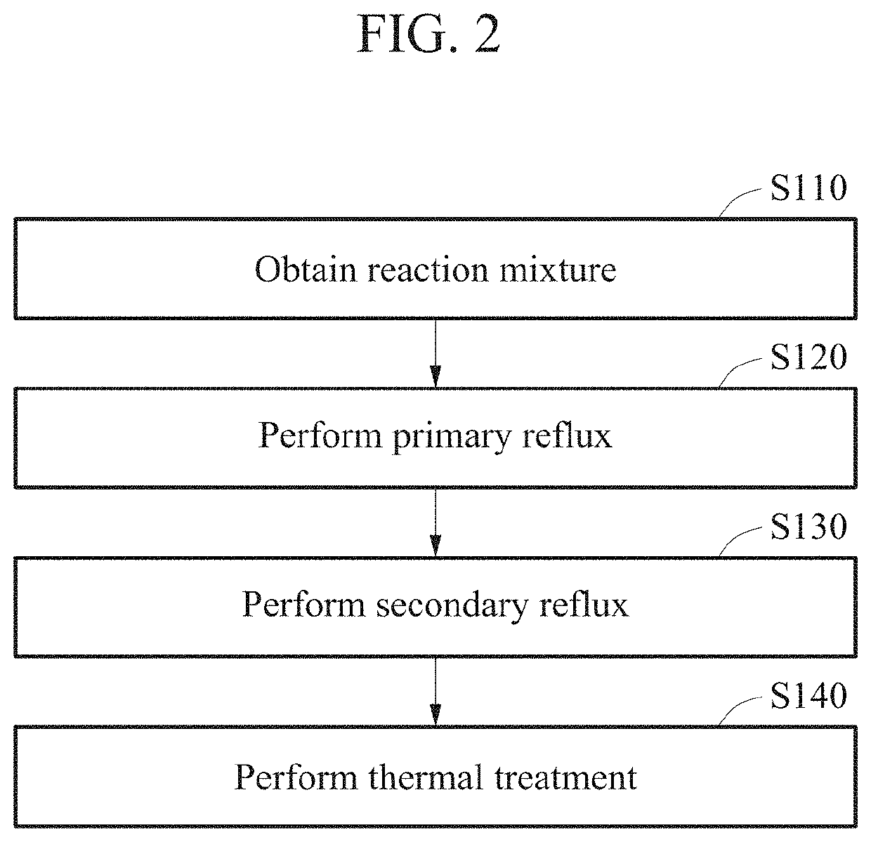
example 1
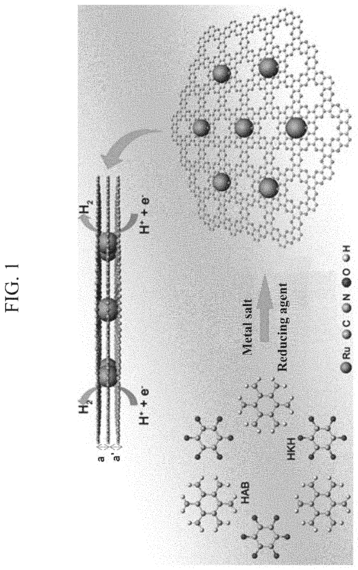
[0096]Manufacturing of catalyst composite (Ru @C2N)
[0097]N-methyl-2-pyrrolidone (NMP) was added to a three-necked flask placed in an ice bath and 1.168 g of RuCl3 anhydride was dissolved. In a nitrogen atmosphere (a general organic synthesis environment), 1.126 g (3.603 mmol) of hexaketocyclohexane (HKH) octahydrate (C6H16O14, molar mass 277.5825) and 1 g (3.603 mmol) of hexaaminobenzene(HAB) trihydrochloride (C6H15C13N6, molar mass 312.18284) were added thereto and followed by reaction for 2 hours. Next, the ice bath was replaced with an oil bath and reflux was performed at 175° C. for 8 hours. After completion of the reaction, cooling was performed up to 80° C. and reflux was performed at 175° C. for 3 hours with 5 g of NaBH4 being added thereto. After cooling to a room temperature, water was added thereto and, as a result thereof, a precipitated black solid product was collected and vacuum filtered using a PTFE membrane (0.5 μm). The remaining material was subject to Soxhlet extr...
examples 2 to 5
[0099]Except that thermal treatment was performed at each of 600° C., 700° C., 800° C., and 1000° C., Ru @C2N catalyst composite was prepared using the same method as that used in Example 1.
experimental example 1
[0102]Measurement of Brunauer-Emmett-Teller (BET) Graph
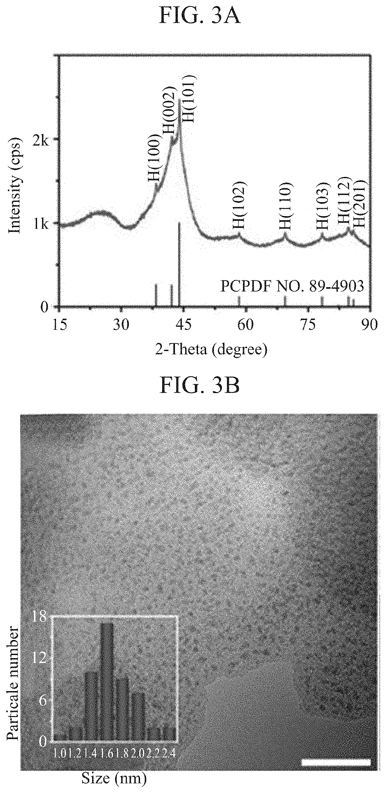
[0103]N2 adsorption / desorption isotherms were measured using the BET method of Example 1 and Comparative Example 1 and were represented in FIGS. 4A and 4B. Referring to FIGS. 4A and 4B, it can be verified that Ru@C2N of Example 1 has the surface area of 400.1 m2 g−1, the pore volume of 0.338 cm3 g−1, and the average spore size of 3.37 nm. The C2N matrix of Comparative Example 1 has the surface area of 280.5 m2 g−1 and the average pore size of 0.83 nm. Accordingly, it can be verified that Ru @C2N of Example 1 has a relatively great surface and pore size compared to the C2N matrix of Comparative Example 1. It is because abundant coordination sites for the uniform distribution of Ru between C2N layers were provided due to growth and nucleation of Ru nano particles within the C2N framework.
PUM
| Property | Measurement | Unit |
|---|---|---|
| Temperature | aaaaa | aaaaa |
| Acidity | aaaaa | aaaaa |
| Particle size | aaaaa | aaaaa |
Abstract
Description
Claims
Application Information