Operational protocol for harvesting a thermally productive formation

a technology of thermally productive formations and operations, applied in the direction of directional drilling, lighting and heating apparatus, borehole/well accessories, etc., can solve the problems of limited utilization, further limitations, and limited disclosure to specifics, and achieve the effect of efficient thermal recovery

Pending Publication Date: 2021-01-07
EAVOR TECH INC
View PDF9 Cites 6 Cited by
  • Summary
  • Abstract
  • Description
  • Claims
  • Application Information

AI Technical Summary

Benefits of technology

[0048]When the operating protocol for harvesting the thermal energy is integrated with the electrical farm aspects, the result is an efficient thermal recovery technology package fully scalable to accommodate electrical user demand using the existing grid without additional footprint and infrastructure requirements saddling conventional electrical distribution.

Problems solved by technology

When the recovery is amalgamated with geothermal energy recovery, with subsequent conversion to heat or electricity, further issues arise which require addressing.
The disclosure is silent regarding casing or liners; however, it is limited to utilization of a fractured zone, angular disposition of the heat absorbing holes being parallel to each other and further limitations.
As a disadvantage, the Moe arrangement would not provide sufficient teaching regarding unrestricted access to a gradient regardless of its anomalies and thus the disclosure is limited to specific scenarios.

Method used


Image

  • Operational protocol for harvesting a thermally productive formation
  • Operational protocol for harvesting a thermally productive formation
  • Operational protocol for harvesting a thermally productive formation

Examples


example 1

Chemical Sealing

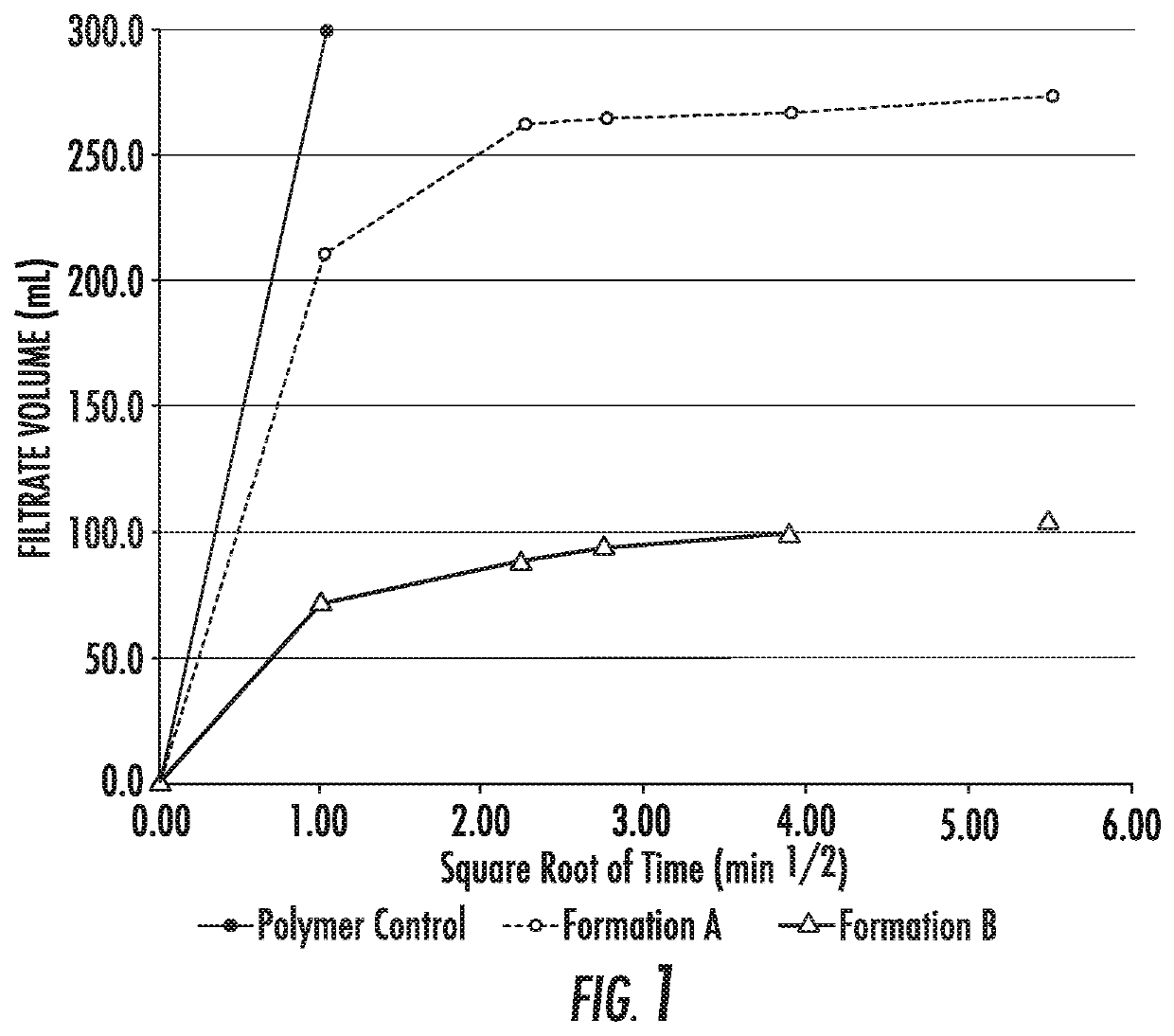
[0145]Initial testing of the sealing capabilities of the silicate system was performed in a permeability plugging apparatus.

[0146]Permeability Plugging Apparatus Tests:[0147]20 μm, 3000 mD discs (provided by OFITE) were soaked in a 30% calcium chloride solution overnight (approximately 16 hours) in order to fully saturate the pores with the brine and create a ‘severe case’ in situ fluid for the silicate drilling fluid with which to react.[0148]Permeability plugging tests (PPT) were run in accordance with OFITE Instruction manual and API RP 13i—Recommended Practice for Laboratory Testing of Drilling Fluids—

250 mL of the test fluids described below was transferred to the PPT cell and a pre-soaked disc was placed in the apparatus. The drilling fluid was allowed to contact the disc for 45 minutes prior to pressurizing the apparatus and beginning the test[0149]The tests were performed for 30 minutes at room temperature and 500 psi[0150]Filtrate volume was recorded after 1...

example 2

[0177]A working fluid was tested consisting of water, a commercially available corrosion inhibitor, potassium bromide, cetyltrimethylammonium surfactant, sodium salicylate, and calcium carbonate solid particulates at 0.5 weight %.

[0178]Measurement of pressure drop (i.e., drag) and characterization of the turbulent flow was tested using a 2″ 200 L capacity heated flow. The loop is equipped with a centrifugal (GIW, LCC-M 50-230) and a progressive cavity (Moyno™, 2F090) pump with high and low shear, respectively. The maximum Re number reaches 500,000 and the loop can operate with 15% volumetric concentration of solid. Pressure drop was calibrated with fresh water and compared to frictional pressure drop at the same flow rate using the working fluid. A turbulent drag reduction of 63% was achieved over a temperature range suitable for direct use heat applications.

[0179]To test reactivity with unspent alkali-silicate in the near-wellbore, Ecodrill™ 317, a 29.1% active solution of 2.5 rati...

example 3

Mechanical Method

[0182]In one embodiment, the mechanism may be effected by adding solid particles to the drilling fluid which migrate naturally into the pore space / fractures to reduce permeability. This is generally known as loss circulation material (LCM).

[0183]The solid particles may be granular materials, fibrous materials and flaked materials and combinations of these and be present (dispersed through drilling fluid) in sizes necessary to reduce permeability. Suitable sizes may be nanometer to millimeter in size.

[0184]Abrams' rule and / or Ideal Packing Theory concepts are useful to establish the most suitable materials. Abrams' rule proposes particle size of the bridging agent should be equal to or slightly greater than ⅓ the medium pore throat size of the targeted formation.

[0185]The ideal packing theory proposes a full range of particle size distribution to effectively seal all voids, including those created by bridging agents.

[0186]Particles may also be sized to penetrate into...


PUM


Abstract

Operational protocol sequences for recovering energy from a thermally productive formation are disclosed. Sealing, drilling, multiranging, power production and distribution techniques in predetermined sequences for well formation are utilized to recover energy regardless of thermal gradient variation, formation depth and permeability and other anomalies or impedances

Description

FIELD OF THE INVENTION[0001]The present invention relates to operational sequences for recovering energy from a thermally productive formation and more particularly, the present invention relates to employing novel techniques in a predetermined sequence to recover energy regardless of thermal gradient variation, formation depth and permeability and other anomalies or impedances.BACKGROUND OF THE INVENTION[0002]In the area of technology directed to harvesting or recovering thermal energy from a thermally productive formation there are factors which require consideration. In thermally productive areas, the geologic parameters play a significant role in the possibility of recovery. The formation may be a high temperature formation, have an irregular / discontinuous / inconsistent thermal gradient, multiple rock types with variable porosity, unconsolidated sand zones among a host of other geologic anomalies. Each of these factors requires a unit operation or series of unit operations to mit...

Claims


Application Information

Patent Timeline
Patent Type & Authority Applications(United States)
IPC IPC(8): F24T10/20E21B43/30E21B33/13
CPCF24T10/20E21B33/13E21B43/30Y02E10/10F24T10/40F24T2010/53F24T50/00F24T2010/56F03G7/04E21B7/04E21B43/305E21B47/0228
Inventor TOEWS, MATTHEWSCHWARZ, BAILEYRIDDELL, DEREKCAIRNS, PAULREDFERN, JOHNCURTIS-SMITH, ANDREWHALE, JONATHANANDREWS, PETER
Owner EAVOR TECH INC
Why Eureka
Try Eureka