Methane and emissions reduction system

a technology of methane and emissions reduction, which is applied in the direction of positive displacement liquid engines, piston pumps, borehole/well accessories, etc., can solve the problems of raising environmental considerations, gas industry faces demonstrable challenges, and it is not feasible to use electric starters

Active Publication Date: 2021-02-25
BHE COMPRESSION SERVICES LLC
View PDF0 Cites 8 Cited by
  • Summary
  • Abstract
  • Description
  • Claims
  • Application Information

AI Technical Summary

Benefits of technology

[0045]In one or more embodiments, these systems may be discrete systems or may overlap in functionality and structure. In various embodiments, the system is designed to reduce raw methane vent and fugitive emissions associated with the system blowdown, packing vents, pneumatic valves, engine start system, and system upset and failures. In one or more embodiments, these components are managed by a control system designed to reduce greenhouse gas emissions between 0-40% (or greater) and in other embodiments between 14-30%.
[0046]In alternate embodiments, the system may be provided as a standalone unit including the full compressor package, while in other embodiments, the system may be provided as a retrofit kit to adapt a pre-existing engine to reduce the emissions thereof. In other words, this system may be paired directly with an external engine, compressor, or compressor package in order to reduce the emissions of that external apparatus, thereby allowing the system to be used with pre-existing units.
[0050]In one or more embodiments, the leak detection system may be operatively connected to the monitoring system and, depending on the configuration, may trigger alarms or actions within the system in the event a leak is detected. In various embodiments, the monitoring system may be programmed to report leakage over a set amount. In related embodiments, the monitoring system may be programmed to take certain action when a leak is detected, including but not limited to sounding an alarm, notifying the operator who can take action, venting the system, turning off (killing) the engine, reducing engine output, or flaring the leaked gas. In a preferred embodiment, vents and louvers will be positioned to direct any escaped gas towards the leak detection components in order to increase the likelihood that a leak will be detected.
[0051]In one or more embodiments, the system comprises an electric motor to replace the natural gas fired reciprocating engine that drives the compressor. By eliminating the engine, the start, engine pre / post-lube, and crankcase vent system emissions are also eliminated. The electric motor drive system may utilize an air system for scrubber level controls and pneumatic valves while electricity is utilized for compressor pre-lube and cooler louver actuator emission elimination.
[0058]In a preferred embodiment, the system is controlled by a software package designed to integrate with the compressor package's programmable logic controller. In one or more embodiments, the instant system may reduce raw methane vent and fugitive emissions associated with the system blowdown, packing vents, pneumatic valves, and engine start system. In one or more embodiments, the system employs low level switches in the scrubbers and / or the fuel filter that can signal an alarm in the event of issues.

Problems solved by technology

Thus, even though methane is one of the cleanest burning fuels, these processes still raise environmental considerations.
The oil & gas industry faces a demonstrable challenge during the production stage, where raw gas is gathered and then delivered to processing plants.
Generally, these regulations have resulted in a reduction in methane emissions from Oil & Gas sites and activities, but the framework limits the emissions reduction focus (at the federal level) to non-methane volatile organic compounds (VOCs) and normal operating emissions, leaving a number of opportunities to further reduce methane.
Conversely, when used in remote locations, it may not be feasible to use an electric starter.

Method used


Image

  • Methane and emissions reduction system
  • Methane and emissions reduction system
  • Methane and emissions reduction system

Examples


example 1

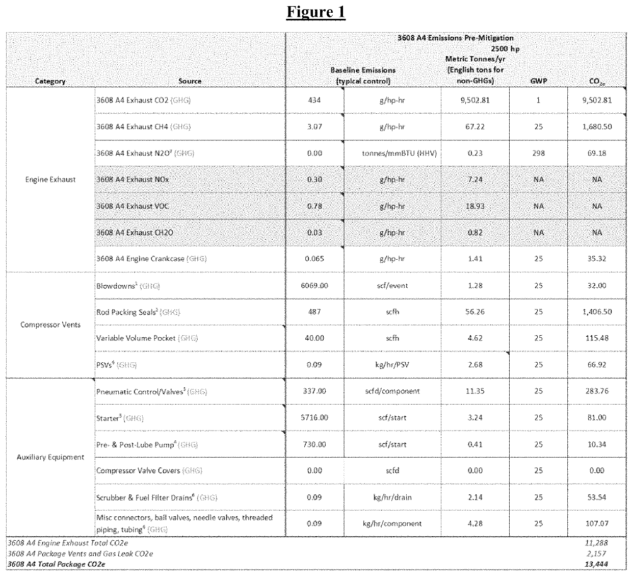
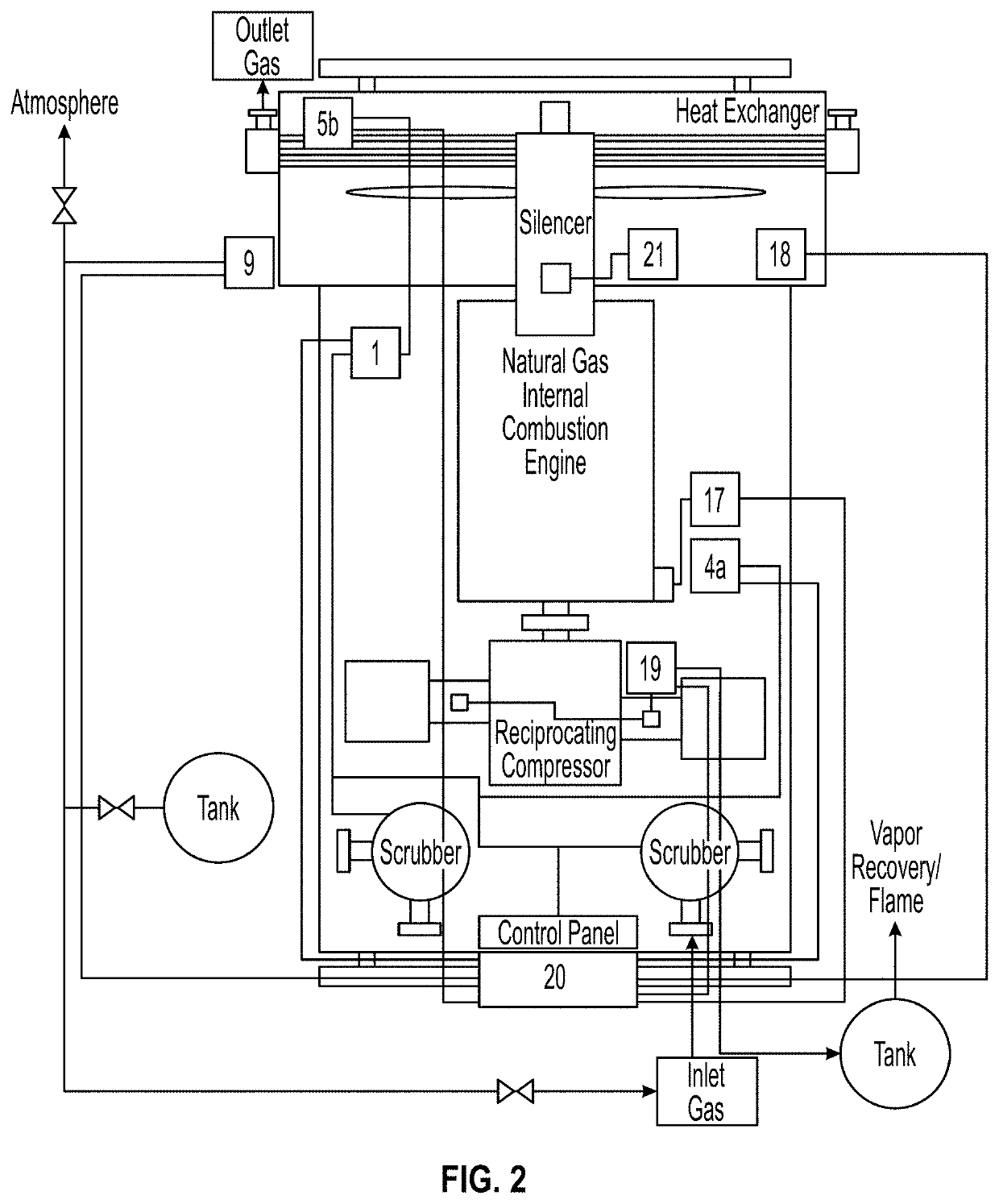
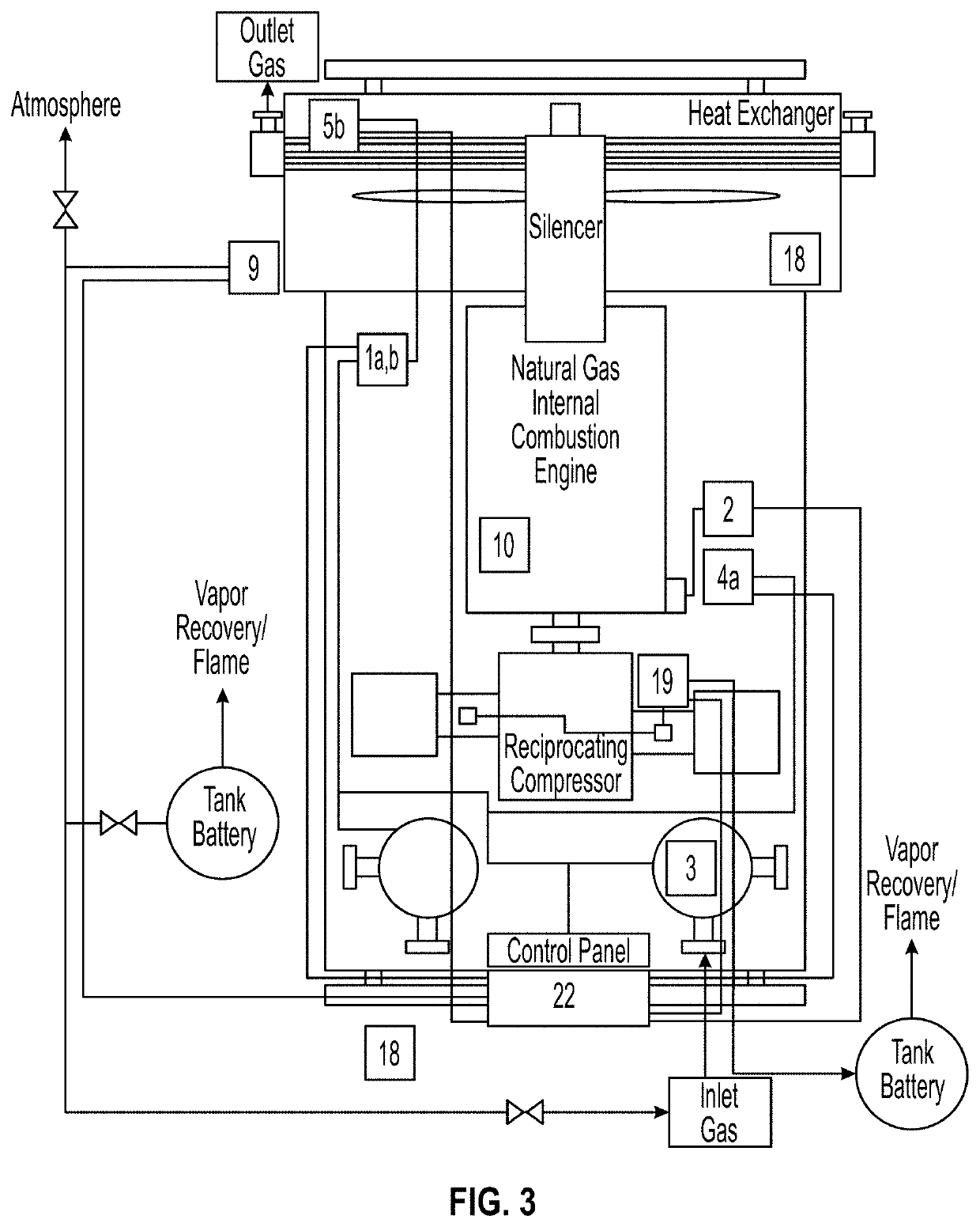
[0116]Experiments were conducted to compare the greenhouse gas emissions produced by the two described embodiments of the instant invention against the Caterpillar 3608 A4 natural gas-fired engine coupled to a four-throw reciprocating Ariel JGC4 compressor, operating at three stages of compression, acting as the control known in the art. The numbers shown in FIG. 1, which are presented in metric tons per year, represent greenhouse gas emissions resulting from combustion, venting and leakage of natural gas of the compressor package operating 24 hours a day, 365 days a year.

[0117]For the purposes of this test, the metrics chosen for comparing the compressor package design are carbon dioxide equivalent in metric tons (CO2e) and methane intensity. CO2e is today's reporting standard for state and federal greenhouse gas reporting and is solely supported on the 100-year GWP Time Horizon. GWP is the Global Warming Potential, and for the purposes of this test, the information provided by IPC...


PUM


Abstract

A system that can eliminate engine combustion emissions in addition to raw and fugitive methane emissions associated with a gas compressor package. The system may comprise an air system for starting and instrumentation air supply; electrically operated engine pre / post-lube pump, compressor pre-lube pump, and cooler louver actuators; compressor distance piece and pressure packing recovery system; blow-down recovery system; engine crankcase vent recovery system; a methane leak detection system; and an overall remote monitoring system.

Description

CROSS REFERENCE TO RELATED APPLICATIONS[0001]This application claims the benefit of U.S. Provisional Application No. 62 / 888,655 filed Aug. 19, 2019 and entitled “Methane and Emissions Reduction System,” and U.S. Provisional Application No. 63 / 047,414 filed Jul. 2, 2020 and entitled “Methane and Emissions Reduction System.”TECHNICAL FIELD[0002]The instant invention relates to the field of gas engine compressors and compressor packages.STATEMENT REGARDING FEDERALLY SPONSORED RESEARCH OR DEVELOPMENT[0003]Not Applicable.REFERENCE TO A “SEQUENCE LISTING,” A TABLE, OR A COMPUTER PROGRAM[0004]Not Applicable.FIGURES[0005]It should be understood that the drawings are not necessarily to scale; instead, emphasis has been placed upon illustrating the principles of the invention. In addition, in the embodiments depicted herein, like reference numerals in the various drawings refer to identical or near identical structural elements.[0006]FIG. 1 is a table showing greenhouse gas emissions for a pa...

Claims


Application Information

Patent Timeline
Patent Type & Authority Applications(United States)
IPC IPC(8): F04B49/10F04B35/00F04B39/12F04B41/00F04B49/06
CPCF04B49/10F04B35/002F04B39/128F05D2260/80F04B49/065F05D2270/08F04B41/00F04B35/04F04B39/02B01D2258/01B01D2258/06B01D2257/7025B01D2258/018B01D53/263E21B47/117E21B43/12E21B43/34F17C2221/035F17C2221/03F17C2221/033F17C5/00F17D1/04F17D1/07F02B63/06
Inventor ROBBINS, MICHAELSTREZO, PETERPUENTES, CARLOS
Owner BHE COMPRESSION SERVICES LLC
Why Eureka
Try Eureka