Organic compound and organic electroluminescent device using the same

a technology of organic electroluminescent devices and organic compounds, which is applied in the direction of luminescent compositions, organic chemistry, chemistry apparatuses and processes, etc., can solve the problems of poor light emission performance, poor thermal stability, and low glass transition temperature, and achieve excellent light emission performance, excellent electron transport ability, and thermal stability.

Active Publication Date: 2021-05-06
SOLUS ADVANCED MATERIALS CO LTD
View PDF0 Cites 2 Cited by
  • Summary
  • Abstract
  • Description
  • Claims
  • Application Information

AI Technical Summary

Benefits of technology

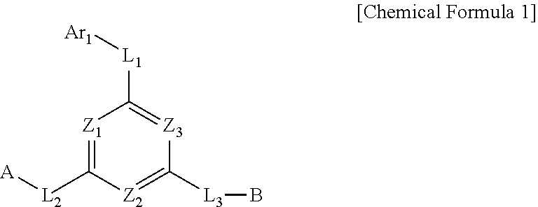
[0024]A compound represented by Chemical Formula 1 may be used as a material for an organic layer of an organic EL device (e.g., a host material of an emissive layer) of an organic EL device by virtue of its excellent electron transporting ability, light emission performance, and thermal stability.
[0025]In addition, by including the compound represented by Chemical Formula 1 as a host material of an emissive layer, the organic EL device according to the present disclosure is excellent in light emission performance, has a low driving voltage, has high stability and long life, and thus may improve the performance and life of full color display panels, as compared to organic EL devices using conventional host materials.

Problems solved by technology

However, conventional materials, despite their good luminescence properties, have low glass transition temperatures and poor thermal stability and thus are not satisfactory in terms of life characteristics of organic EL devices.

Method used


Image

  • Organic compound and organic electroluminescent device using the same
  • Organic compound and organic electroluminescent device using the same
  • Organic compound and organic electroluminescent device using the same

Examples


fabrication example 1

FABRICATION OF COMPOUND A-1

[0090]

[0091]3-phenyl-9H-carbazole (3 g, 12.3 mmol), 9-(4-chloro-6-phenyl-1,3,5-triazin-2-yl)-9H-carbazole (4.8 g, 13.5 mmol), Pd2(dba)3 (0.6 g, 0.6 mmol), (t-Bu)3P (0.3 g, 1.3 mmol), and NaOt-Bu (2.4 g, 24.6 mmol) were added to Toluene (100 ml), and heated to reflux for 12 hours. After the reaction was completed, the organic layer was extracted by using methylene chloride, MgSO4 was added thereto and the organic layer was filtered. After removing the solvent from the filtered organic layer, the target compound, Compound A-1 (5.5 g, yield 80%), was obtained through column chromatography.

[0092][LCMS]: 564

fabrication example 2

FABRICATION OF COMPOUND A-2

[0093]

[0094]3 -phenyl-9H-carbazole (3 g, 12.3 mmol), 9-(4-chloro-6-phenyl-1,3,5-triazin-2-yl)-3-phenyl-9H-carbazole (5.9 g, 13.5 mmol), Pd2(dba)3 (0.6 g, 0.6 mmol), (t-Bu)3P (0.3 g, 1.3 mmol), and NaOt-Bu (2.4 g, 24.6 mmol) were added to Toluene (100 ml), and heated to reflux for 12 hours. After the reaction was completed, the organic layer was extracted by using methylene chloride, MgSO4 was added thereto and the organic layer was filtered. After removing the solvent from the filtered organic layer, the target compound, Compound A-2 (6.1 g, yield 78%), was obtained through column chromatography.

[0095][LCMS]: 640

fabrication example 3

FABRICATION OF COMPOUND A-3

[0096]

[0097]3 -phenyl-9H-carbazole (3 g, 12.3 mmol), 9-(4-(3 -chlorophenyl)-6-phenyl-1,3,5-triazin-2-yl)-3-phenyl-9H-carbazole (6.9 g, 13.5 mmol), Pd2(dba)3 (0.6 g, 0.6 mmol), (t-Bu)3P (0.3 g, 1.3 mmol), and NaOt-Bu (2.4 g, 24.6 mmol) were added to Toluene (100 ml), and heated to reflux for 12 hours. After the reaction was completed, the organic layer was extracted by using methylene chloride, MgSO4 was added thereto and the organic layer was filtered. After removing the solvent from the filtered organic layer, the target compound, Compound A-3 (6.9 g, yield 79%), was obtained through column chromatography.

[0098][LCMS]: 716


PUM

PropertyMeasurementUnit
current densityaaaaaaaaaa
Chemical Formulaaaaaaaaaaa
asymmetric structureaaaaaaaaaa

Abstract

The present disclosure relates to a novel organic compound which has excellent thermal stability, electron transporting ability, and light emitting ability, and to an organic EL device containing the same. As the organic compound is used in an organic material layer of the organic EL device, the thermal stability, luminous efficiency, driving voltage, and life of the device can be improved.

Description

TECHNICAL FIELD[0001]The present disclosure relates to a novel organic compound and an organic electroluminescent device using the same, and more particularly, to a compound having excellent thermal stability and electron transporting ability, and an organic electroluminescence device improved in terms of luminous efficiency, driving voltage, life, etc. by including the compound in one or more organic layers.BACKGROUND ART[0002]In organic electroluminescence devices (hereinafter, “EL devices”), upon application of voltage between two electrodes, holes are injected from an anode to an organic layer and electrons are injected from a cathode into the organic layer. Injected holes and electrons meet each other to form excitons, and light emission occurs when the excitons fall to a ground state. In this case, materials used for the organic layer may be classified into, for example, luminescent materials, hole injection materials, hole transporting materials, electron transporting materia...

Claims


Application Information

Patent Timeline
Patent Type & Authority Applications(United States)
IPC IPC(8): H01L51/00C07D403/14C09K11/06C07D405/14C07D409/14
CPCH01L51/0067C07D403/14C09K11/06H01L51/0072H01L51/0052H01L51/5016C07D405/14H01L51/0073C07D409/14H01L51/0074H01L51/0054C07D209/86H10K85/615H10K85/654H10K85/6576H10K85/6574H10K85/6572H10K50/11H10K2101/10C09K2211/1029C09K2211/1059C09K2211/1018H10K85/622
Inventor SON, HO JUNKIM, YOUNG BAEBAE, HYUNG CHAN
Owner SOLUS ADVANCED MATERIALS CO LTD
Why Eureka
Try Eureka