Negative electrode for lithium secondary battery, lithium secondary battery comprising same, and manufacturing method therefor

a secondary battery and negative electrode technology, applied in the manufacturing process of electrodes, electrochemical generators, cell components, etc., can solve the problems of reducing the battery capacity, large initial irreversible capacity, so as to suppress the loss of lithium or side reaction of lithium, reduce the resistance, and reduce the effect of battery capacity

Pending Publication Date: 2021-08-05
LG ENERGY SOLUTION LTD
View PDF0 Cites 0 Cited by
  • Summary
  • Abstract
  • Description
  • Claims
  • Application Information

AI Technical Summary

Benefits of technology

The present invention provides a negative electrode with a lithium diffusion rate control layer to improve cycle characteristics and prevent loss of lithium or side reaction. The manufacturing method also uses a very thin layer of the lithium diffusion rate control layer to minimize resistance increase.

Problems solved by technology

As a result, an initial irreversible phenomenon is caused and the electrolyte capacity is depleted in the course of continuous charge / discharge, thereby reducing the battery capacity.
In addition, although the silicon-based material shows a high capacity, a problem arises in that the initial irreversible capacity is large.
In the case of the silicon negative electrode active material, a large amount of lithium inserted into the negative electrode does not return to the positive electrode at the time of initial charging and thus the initial irreversible capacity becomes large.
When the initial irreversible capacity increases, there occurs a problem that the battery capacity and the cycle are rapidly reduced.
However, in the manufacture of a lithium secondary battery, it often happens that time is delayed when electrolyte is injected or until initial charge and discharge after cell assembly.
Herein, before the injection of the electrolyte, lithium of the lithium layer attached to the negative electrode may be unevenly moved into the electrode (solid-diffusion), thereby increasing resistance, or lithium may be diffused into the air, causing a problem of loss of lithium amount.
The proposed technology is intended to prevent an accident such as a fire during the prelithiation process, but the technology does not recognize problems such as a lithium loss which occurs as the time until the electrolyte injection is delayed after laminating a lithium metal thin film on the negative electrode.
Further, since the thickness of the anti-lithiation layer is 0.5 to 5 μm, which is high, it causes a problem that deteriorates the battery performance by increasing the resistance.

Method used


Image

  • Negative electrode for lithium secondary battery, lithium secondary battery comprising same, and manufacturing method therefor
  • Negative electrode for lithium secondary battery, lithium secondary battery comprising same, and manufacturing method therefor
  • Negative electrode for lithium secondary battery, lithium secondary battery comprising same, and manufacturing method therefor

Examples


example 1

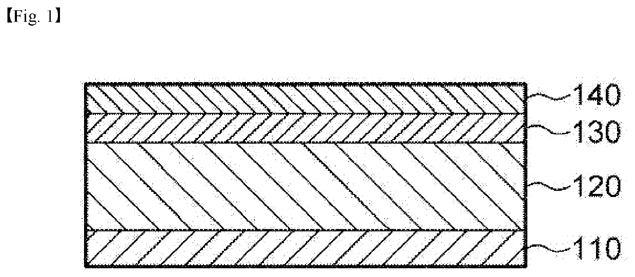
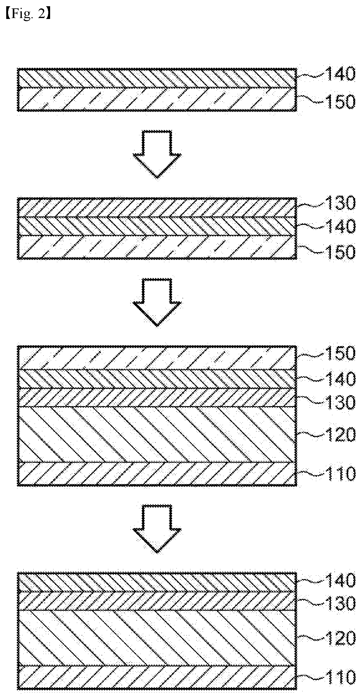
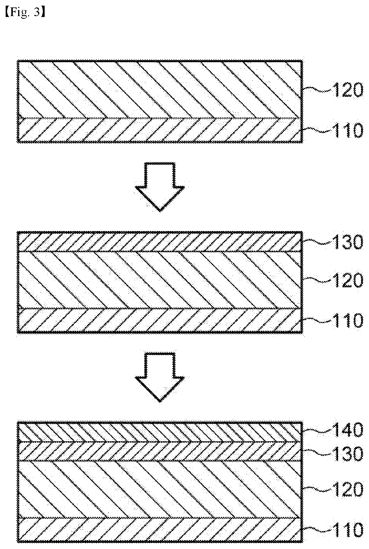
[0105]Fabrication of Negative Electrode with Lithium Diffusion Rate Control Layer and Lithium Layer

[0106]The negative electrode of the above preparation example was placed in a chamber (150° C., 0.1 torr), and trimethylaluminum and H2O gas were injected with a pressure of 1 torr nitrogen gas at a ratio of 17:1. The atomic layer deposition process was repeatedly performed until the thickness of the Al2O3 layer became about 3 nm on the negative electrode mixture layer by the following reactions (A) and (B).

Al—OH*+Al(CH3)3+Al—O—Al(CH3)2*+CH4  (A)

Al—CH3*+H2O+Al—OH*+CH4  (B)

[0107]Then, a negative electrode was prepared by laminating a lithium thin film having a thickness of 10 μm.

[0108]Preparation of Half Coin Cell

[0109]Coin cells were prepared in the order of negative electrode / separator (porous film made of polypropylene (20 μm, Celgard)) / lithium foil by using lithium foil and stainless steel upper and lower plates as counter electrodes of the obtained negative electrode and prepared n...

example 2

[0110]A battery was manufactured in the same manner as in Example 1, except that the injection time of the electrolyte was changed to a time after 2 hours from the assembly of the coin cell.

example 3

[0113]Preparation Example of Positive Electrode

[0114]LiCoO2 SBR binder, CMC and acetylene black as the positive electrode active material were added to water in a weight ratio of 93:3:1.5:2.5 to prepare a positive electrode mixture. The mixture was uniformly coated on 10 μm aluminum foil and dried for 12 hours in a 50° C. vacuum oven to prepare a positive electrode.

[0115]Preparation of Mono Cells

[0116]1-stack mono cells were prepared in the order of a negative electrode / separator (polypropylene material porous film; 20 μm, Celgard) / positive electrode, using a positive electrode and a negative electrode having a lithium diffusion rate control layer and a lithium layer prepared in Example 1. The electrolyte was injected after 2 hours from the assembly of the mono cells At this time, the electrolyte is a mixture of ethylene carbonate and ethyl methyl carbonate in a mass ratio of 3:7.


PUM

PropertyMeasurementUnit
thicknessaaaaaaaaaa
thicknessaaaaaaaaaa
thicknessaaaaaaaaaa

Abstract

A negative electrode for a lithium secondary battery including a current collector; a negative electrode mixture layer disposed on at least one surface of the current collector; a lithium diffusion rate-controlling layer formed on a surface of the negative electrode mixture layer by atomic layer deposition opposite the current collector; and a lithium layer disposed on a surface of the lithium diffusion rate-controlling layer opposite the negative electrode mixture layer. A method for prelithiating the negative electrode for a lithium secondary battery and a method for manufacturing a lithium secondary battery comprising the negative electrode. The negative electrode includes a lithium diffusion rate-controlling layer between a lithium thin film and a negative electrode mixture layer, and thereby can control the lithium diffusion rate during a prelithiation process and inhibit lithium loss or side reactions of lithium, thus enhancing cycle characteristics.

Description

TECHNICAL FIELD[0001]This application claims the benefit of priority based on Korean Patent Application No. 10-2018-0132011, filed on Oct. 31, 2018, and the entire contents of the Korean patent application are incorporated herein by reference.BACKGROUND ART[0002]As the price of energy sources increases due to depletion of fossil fuels and the interest in environmental pollution increases, the demand for environmentally friendly alternative energy sources becomes an indispensable factor for future life. Especially, as technology development and demand for mobile devices are increasing, demand for secondary batteries as energy sources is rapidly increasing.[0003]Typically, in terms of the shape of the battery, there is a high demand for a prismatic secondary battery and a pouch-type secondary battery that can be applied to products such as mobile phones with a small thickness. In terms of materials, there is a high demand for lithium secondary batteries such as lithium ion batteries a...

Claims


Application Information

Patent Timeline
Patent Type & Authority Applications(United States)
IPC IPC(8): H01M4/36H01M10/052H01M4/38H01M4/04C23C16/455H01M4/48H01M4/62H01M4/134H01M4/1395C23C16/40H01M10/058
CPCH01M4/366H01M10/052H01M4/382H01M4/0428C23C16/45555H01M4/364H01M2004/027H01M4/62H01M4/134H01M4/1395C23C16/403H01M10/058H01M4/483C23C16/45525H01M4/587H01M4/133H01M4/1393C23C16/405H01M2004/021H01M4/0404H01M4/04H01M4/131H01M4/1391H01M4/625Y02E60/10H01M4/13H01M4/139H01M4/0447H01M10/446C23C16/4408C23C16/40C23C16/308
Inventor HONG, YEON SUKKIM, JU RI
Owner LG ENERGY SOLUTION LTD
Why Eureka
Try Eureka