
Integration of dr plant and electric dri melting furnace for producing high performance iron

Pending Publication Date: 2021-09-30
MIDREX TECH INC
View PDF3 Cites 0 Cited by
  • Summary
  • Abstract
  • Description
  • Claims
  • Application Information

AI Technical Summary

Benefits of technology

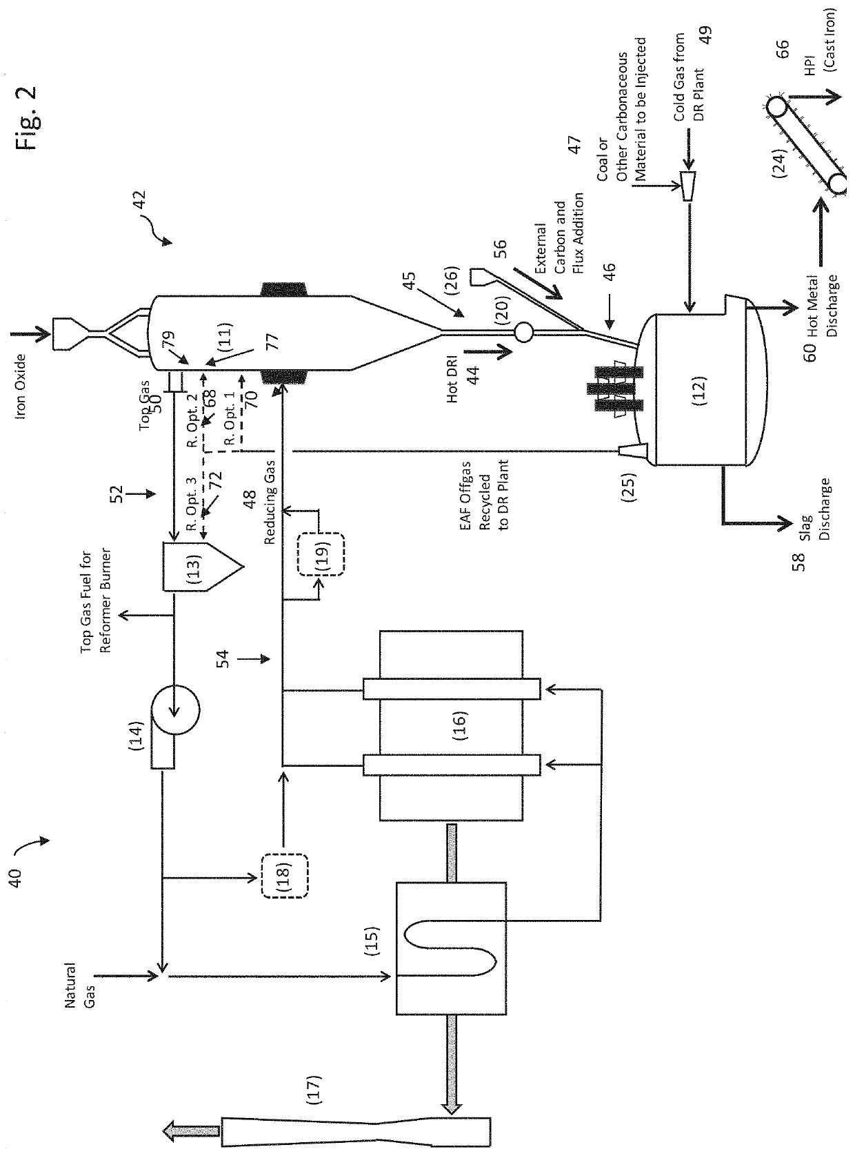
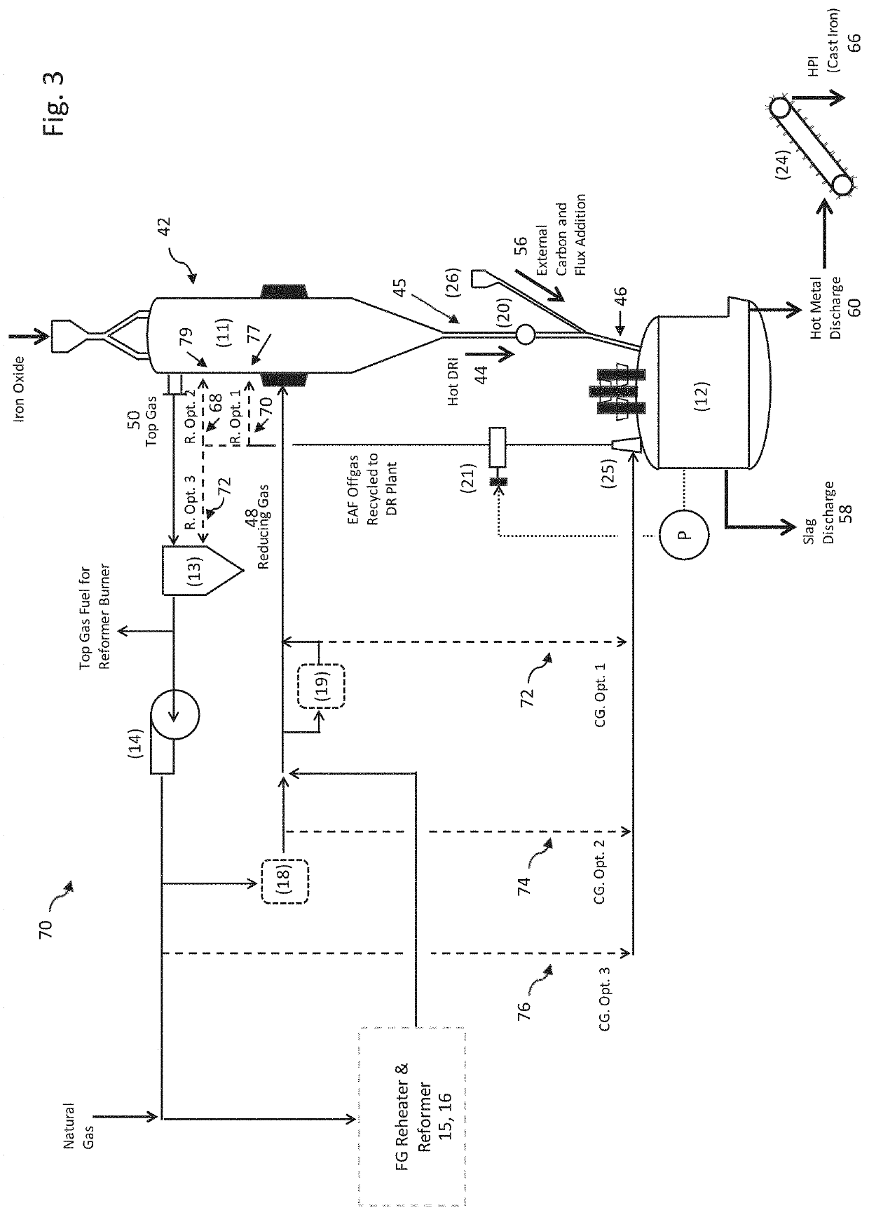
The present invention is about a method and system for integrating the melting step with the production step of DRI. The aim is to improve the processing of a wider range of iron ores, especially lower grade ones, while maintaining high energy efficiency, material yield, and productivity. The invention achieves the following objectives: 1) maintaining a stable reducing atmosphere in the DRI melting furnace to prevent air infiltration and explosions; 2) maintaining higher residual carbon in the DRI without causing fines loss during handling between the DR plant and the DRI melting furnace, especially when using DRI with high carbon content; and 3) efficiently using the chemical and sensible energy in the offgas from the DRI melting furnace.

Problems solved by technology

However, high-quality steel product equivalent to what is commonly termed BF grade product restricts the amount of tramp element such as copper derived from the scrap.
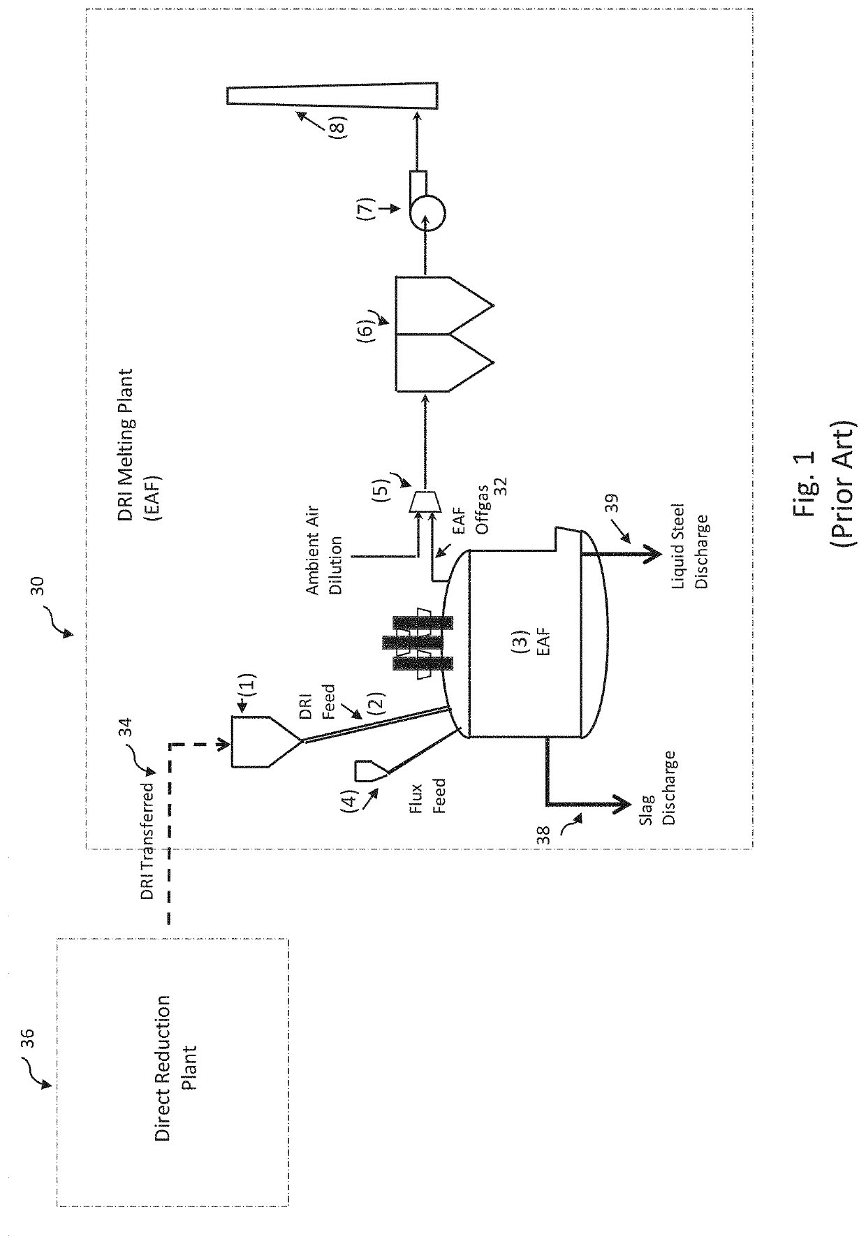
However, unlike the BF process, the gangue contained in the iron ore cannot be removed under solid-gas reaction within the prevalent direct reduction processes employed presently.
DRI containing higher acid gangues is not preferable at the EAF since a larger amount of slag increases the operation cost and decreases the productivity.
However, the depletion of the DR grade iron ore is a concern for the future, which may negatively impact the productions shift from BF-BOF to EAF progresses.
However, in the case of using the DRI made of lower grade oxide pellets with conventional EAF to produce liquid steel or HPI, the higher gangue content in the DRI increases the slag volume, which increases the operating cost and decreases the productivity at EAF, as explained below.
The additional slag leads to the higher iron yield loss since some iron will be lost in the form of FeO saturated in the slag at more than 20% under the oxidizing atmosphere at the EAF.
These larger slag volumes also increase the electrical consumption and the slag removal efforts, which results in a longer tap to tap time and lower productivity at the EAF.

Method used


Image

  • Integration of dr plant and electric dri melting furnace for producing high performance iron
  • Integration of dr plant and electric dri melting furnace for producing high performance iron
  • Integration of dr plant and electric dri melting furnace for producing high performance iron

Examples


Embodiment Construction

[0020]To reduce the slag volume in producing HPI, it is advantageous to apply a two step process; firstly producing the hot metal or cold pig iron after melting the DRI and removing the slag, and secondarily decarburizing the carbon in the first iron product and producing the liquid steel with the additional scrap in a separate melting furnace downstream. The first melting step of DRI can be similar to what the conventional blast furnace practices; i.e. producing the hot metal with the lower grade iron ore under the reducing atmosphere to maintain FeO %<1% in the slag and the slag basicity of about 1.0 to 1.3 lower than the case of the steelmaking at EAF.

[0021]To maintain a lower FeO % under the reducing atmosphere, the carbon dissolved in the molten hot metal must be high enough, typically around 4%. To achieve this level, the residual carbon amount in DRI should be high enough since the carbon material added externally to make up the carbon results in the lower yield at the EAF, d...


PUM

PropertyMeasurementUnit
Temperatureaaaaaaaaaa
Pressureaaaaaaaaaa
Angleaaaaaaaaaa

Abstract

A direct reduction process comprises providing a shaft furnace of a direct reduction plant to reduce iron oxide with reducing gas; providing a direct reduced iron melting furnace; and coupling a discharge chute between a discharge exit of the direct reduced shaft furnace and an inlet of the direct reduced iron melting furnace; wherein direct reduced iron and the reducing gas from the shaft furnace flow through the discharge chute and the reducing gas controls the melting furnace atmosphere to reducing environment.

Description

CROSS-REFERENCE TO RELATED APPLICATION[0001]The present non-provisional patent application claims the benefit of priority of U.S. Provisional Patent Application No. 62 / 993,787, filed on Mar. 24, 2020, and entitled “MIDREX PROCESS FOR PRODUCING HIGH PERFORMANCE IRON,” the contents of which are incorporated in full by reference herein.TECHNICAL FIELD[0002]The present invention relates generally to the direct reduced iron (DRI) and steelmaking fields, where DRI is commonly understood to include cold direct reduced iron (CDRI), hot direct reduced iron (HDRI), and hot briquetted iron (HBI). More specifically, the present invention relates to a method and system to integrate the melting step of a DRI production process with the DRI production step.BACKGROUND[0003]The blast furnace (BF)-basic oxygen furnace (BOF) process route has been the most predominant method globally for producing crude steel, but is a major source for CO2 emissions. Steelmaking with an electric arc furnace (EAF) usin...

Claims


Application Information

Patent Timeline
IPC IPC(8): C21B13/00C21B13/12C21B13/02C21B13/14
CPCC21B13/0073C21B13/12C21B13/023C21B2100/66C21B13/0093C21B2100/44C21B2100/64C21B13/14C21B13/143C21B13/002C21B13/02Y02P10/20Y02P10/134C21C5/52
Inventor ASTORIA, TODD MICHAELMICHISHITA, HARUYASU
Owner MIDREX TECH INC
Learn More