Non-hydration strength in cementitious compositions

a non-hydration strength and composition technology, applied in the direction of liquid ingredients supply apparatus, chemistry apparatus and processes, liquid ingredients preparation apparatus, etc., can solve the problems of not being able to achieve high green strength or extended “finishing” and achieve significant window of finishing, improve the 1- and 7-day strengths

Pending Publication Date: 2021-11-18
GCP APPL TECH INC
View PDF0 Cites 6 Cited by
  • Summary
  • Abstract
  • Description
  • Claims
  • Application Information

AI Technical Summary

Benefits of technology

[0185]This highlights the advantage of the present invention: because one can see from these results that finishing activities can begin earlier, because, more importantly, the window of finishing is extended significantly.
[0186]The strengths for each mix are shown in FIG. 10B. Although the strength for MIX 1 was less than REF 1, at 28 days, the strengths were comparable. The use of accelerators (e.g. calcium nitrate) can help to improve the 1- and 7-day strengths, if desired.Example 6
[0187]In this example, six concrete mixes were made, each containing 500 pounds per cubic yard lbs / yd3 of cement, 1800 lbs / yd3 of stone, 1425 lbs / yd3 of sand, 300 lbs / yd3 of water and 4.5 oz / cwt of WRDA® 64, a low-range water reducer (LRWR). For mixes MIX 2-4, 1.8% s / c of an AMPS monomer, 0.2% s / c of a bis-AAm cross-linker and 0.26% s / c of KPS were added with the cement.
[0188]For mixes designated as REF 2-4, no additional chemicals were added.
[0189]All concretes were mixed according to the protocol of Example 5. For the mixes MIX 2-5, 0.2% s / c sodium bi-sulfite was added after the rest period. After mixing, a portion of each concrete was tested for slump (according to ASTM C143-15a), air content (according to ASTM C231-17a), while the remaining concrete was poured into a 2-foot by 3-foot by 8-inch slab, and then the surface was screed and hand-floated. Three mixes were made using exemplary methods of the invention while three mixes were used as a reference. The three slabs per mix design combined to provide a larger area over which to perform a foot print test, which allowed more foot prints to be imprinted within a given time period. According to ACI 302, the concrete should be finished when the depth reaches ¼″.
[0190]As shown in FIG. 11, the depth of a footprint (created with one foot and waiting for 5 seconds), is shown versus time for each set (MIX 2-4 versus REF 2-4). For MIX 2-4, the penetration achieves and maintains a level of around ¼″ for a much wider range (lightly shaded area) than REF 2-4 (darkly shaded area). Both the slumps and air contents of each were comparable (5-6″ slump, 2-3% air).Example 7

Problems solved by technology

It does so without relying on conventional thickeners or thixotropy agents, which, in the past, have not been sufficient for extended “finishing” or the attainment of high green strength.

Method used


Image

  • Non-hydration strength in cementitious compositions
  • Non-hydration strength in cementitious compositions
  • Non-hydration strength in cementitious compositions

Examples


example 1

[0163]Hydratable cement mortar samples were prepared using incremental amounts, e.g., 2%, 4%, and 6% solids based on weight of cement material (% s / cm), of 2-acrylamido-2-methylpropane sulfonic acid (“AMPS”) monomer and N,N′-methylene bis(acrylamide) (“bis-AAm”) cross-linker monomer in a weight ratio (AMPS / bis-AAm) of 90 / 10.

[0164]The cement mortar mix design included cement, water, and a sand (EN-196) in a weight ratio (sand / cement / water) of 1350 / 533 / 240 grams (w / cm=0.45), and also including a polycarboxylate dispersant polymer at 0.06% s / cm based on weight of cement.

[0165]The polymerization initiator system employed was a potassium persulfate (“KPS”) initiator (0.026% s / cm) with a sodium bisulfite activator (0.012% s / cm) to form the redox pair.

[0166]Mixing procedure was as follows: 1) sand, water, AMPS, bis-AAm, and KPS were added into a Hobart mixer bowl and mixed for 2 minutes; 2) cement was added to the bowl, and mixed for an additional 2 minutes; and 3) sodium bisulfite was the...

example 2

[0171]Cement mortar mixes using different monomers were prepared in a manner similar to that described above in Example 1.

[0172]In this example, two different exemplary compositions of the present invention were tested: AMPS and acrylic acid (AA); and AMPS and N,N′-dimethylacrylamide (DMA). The materials and mixing procedure were similar to that described above in Example 1, except the types, combinations, and relative amounts of the monomers are slightly varied: (1) AMPS:AA:bis-AAm=1.8:2.0:0.2% s / cm, (2) AMPS:DMA:bis-AAm=1.8:2.0:0.2% s / cm, and (3) AMPS:DMA:bis-AAm=0.9:0.1:3.0% s / cm.

[0173]The same KPS / sodium bisulfite redox pair was used for each of the three mixes.

[0174]In FIG. 7, the penetration test results show that the AMPS combination with polymerizable monomers such as AA or DMA results in equal or better plateau compressive strengths as the AMPS system of Example 1 with comparable dose.

example 3

[0175]A cement mortar mix using the same AMPS / bis-AAm system in Example 1 was tested again, this time with the addition of calcium nitrate at 1.42% s / cm. The same KPS / sodium bisulfite redox pair was also used. The mortar mix were prepared in the same manner as Example 1.

[0176]As shown in FIG. 8, the addition of calcium salt enhanced the plateau compressive strength compared to the respective mix in Example 1. It should be noted that the addition of calcium or other alkaline salts also increases the later age strength that originates from cement hydration.


PUM

PropertyMeasurementUnit
penetration pressureaaaaaaaaaa
depthaaaaaaaaaa

Abstract

Described are compositions and methods for controlled strength development in a hydratable cementitious material, and more particularly to the use of polymerizable monomer components, which are initiated and activated by a redox pair which are mixed in controlled fashion, for enhancing non-hydration strength within the matrix of the plastic hydratable cementitious material before setting of the cementitious material begins. Exemplary applications include minimizing pressures on formwork for high fluid ready-mix applications, enhancing support and bonding properties for integrated concrete slab work and other sequential applications, or facilitating speedy 3D printing applications, among other unique possibilities.

Description

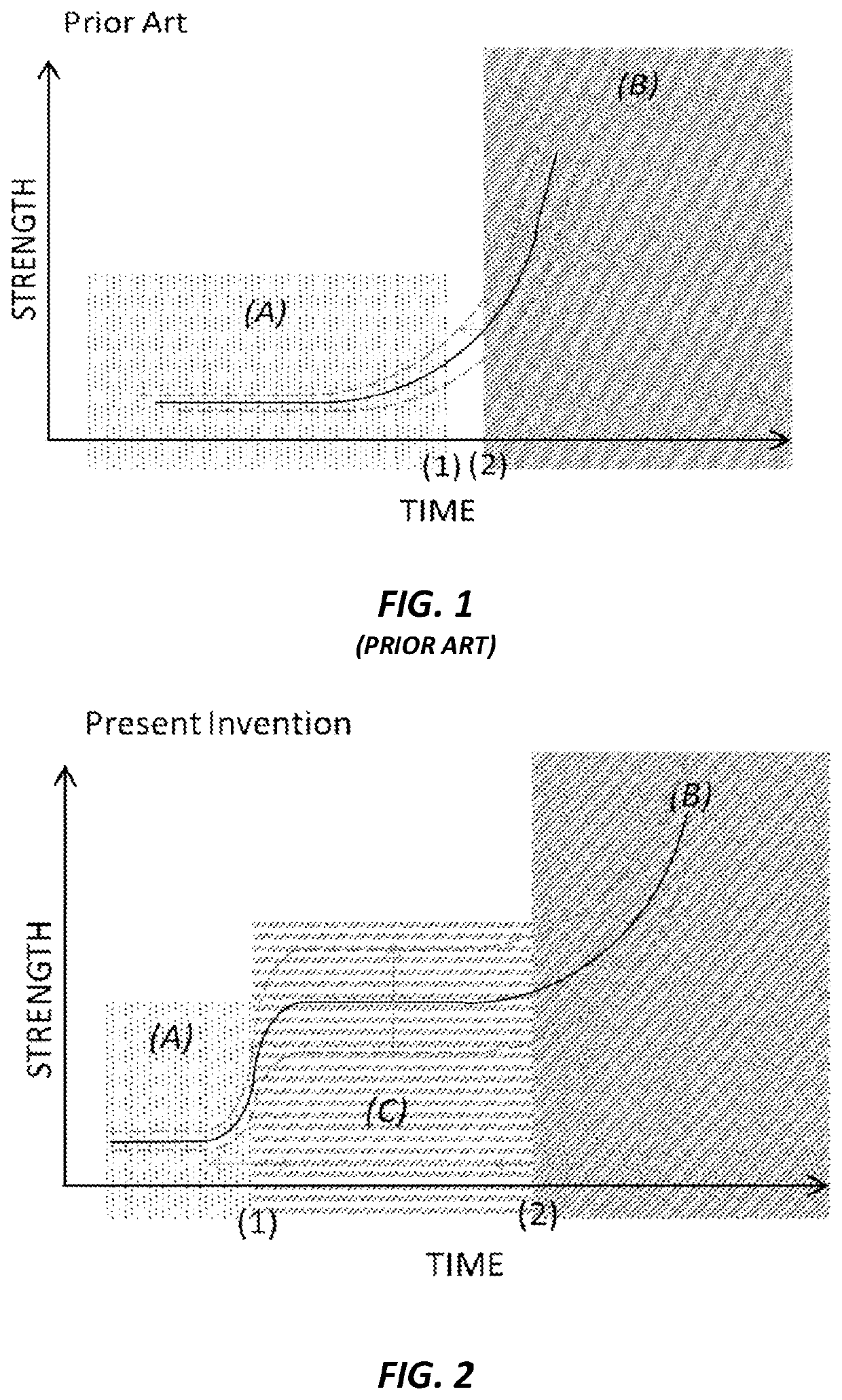
FIELD OF THE INVENTION[0001]The present invention relates to controlled strength development in a hydratable cementitious material, and more particularly to the use of a polymerizing system within the matrix of the plastic hydratable cementitious material to increase non-hydration strength before setting of the cementitious material begins.BACKGROUND OF THE INVENTION[0002]Concrete contains hydraulic material (Portland cement) for binding together aggregates. Upon mixing with water, the cement binder begins to hydrate, and the hydrating concrete can be poured or formed into molds or formwork. The hydrating concrete will then eventually set into a pavement, foundation, slab, wall, pipe, or other structural shape.[0003]FIG. 1 (PRIOR ART) illustrates graphically the strength of concrete (indicated along vertical axis at left) as the concrete is being transported from a batch plant towards a delivery (pour) site. During transport, the concrete will be in a fluid liquid state, as designat...

Claims


Application Information

Patent Timeline
Patent Type & Authority Applications(United States)
IPC IPC(8): C04B28/04B33Y70/10C04B40/00C04B24/26B28C7/12B28C5/42C04B22/14
CPCC04B28/04B33Y70/10C04B40/0028C04B24/2652B33Y80/00B28C7/128B28C5/4258C04B22/14C04B24/2647C04B28/02C04B2111/00181C04B2111/00155C04B2103/0062C04B24/163C04B2201/05B33Y10/00C04B14/06C04B22/147C04B24/16C04B2103/0095C04B2103/0096C04B22/068C04B40/065B33Y30/00
Inventor CHUNG, BYONG-WATREGGER, NATHAN A.BERODIER, ELISEBURNS, ELIZABETHROCHA, ERNIEWILSON, EZGIROBERTS, MARK F.
Owner GCP APPL TECH INC
Why Eureka
Try Eureka