Eureka AIR delivers breakthrough ideas for toughest innovation challenges, trusted by R&D personnel around the world.

Lithium-ion primary pouch battery

Pending Publication Date: 2021-12-09
SAFT AMERICA INC
View PDF1 Cites 0 Cited by
  • Summary
  • Abstract
  • Description
  • Claims
  • Application Information

AI Technical Summary

Benefits of technology

The disclosed embodiments describe a new type of battery pouch that can provide more energy than regular lithium-ion cells, while being flexible, light, and operable over a wide range of temperatures. It can also be monitored for functionality periodically.

Problems solved by technology

A drawback of such lithium cells arises from the highly reactive nature of lithium metal in air.
The preparation of metallic lithium anodes can be cumbersome, expensive and may also be hazardous.
Another drawback of primary lithium cells is encountered in high-power primary lithium cell designs where a thin metallic lithium anode is required.
A common problem in such high power cells is the low tensile strength of metallic lithium.
The first approach (excess lithium) markedly reduces the practical energy density (available energy per volume unit) achievable by the cell.
The second approach (using a thin conducting support) may markedly complicate the anode manufacturing process because a vacuum deposition method or other similar manufacturing methods may have to be used to deposit the thin layer of metallic lithium on the conducting support.
Such techniques are inefficient for mass production processes, may require costly equipment, and may have to be performed in batch.
A first drawback is a very high self-discharge rate of the resulting cells (typically about 5% of the cell's charge per month).
While such a high self-discharge rate value may be commercially acceptable for rechargeable lithium cells, it is not acceptable for most of primary lithium cells for which a loss of up to 0.1% of the cell's charge per month is typically required.
A second drawback is they typically have a low energy density as compared to primary lithium cells.
Typically, a quality of the lithium layer deposited or plated on the anode during the charging of the cell may not be good enough for many charge discharge cycles.
Unfortunately, lithium dendrite formation limits the number of permissible charging / discharge cycles, as eventually the dendrites may contact the cathode which may result in cell failure.
Dendritic lithium formation in rechargeable cells may thus make such cells inherently less stable since, if such a cell short-circuit occurs, the cell may explode.
As a result, the amount of the remaining lithium available in the cell decreases, reducing the practically achievable energy density of the cell.
However, using excess of lithium in the cell increases the thickness of the anode and therefore undesirably decreases the practically achievable energy density of the cell.
Moreover, using a larger quantity of lithium is inherently more dangerous, decreasing overall cell safety, and, as lithium is a comparatively expensive metal, increasing the cell's cost.
However, side reactions with the electrolyte may lead to lithium loss in the anode and may ultimately cause cell failure.
In other words, the deposition of highly reactive lithium metal on the carbonaceous anode of such prior art lithium cells is problematic.
However, the cylindrical cell design has certain drawbacks or disadvantages, such as being heavy and having low packaging density due to space cavities.
Further, as explained herein below, an external pressure cannot easily be applied on a cylindrical cell.
Disadvantages of thermal batteries can include, for example, short activated life, relatively high external surface temperature during use because of the pyrotechnic thermal energy source, non-linear output voltage, inability to test functionality (e.g., an open-circuit voltage (OCV) test), and one-time use.

Method used


Image

  • Lithium-ion primary pouch battery
  • Lithium-ion primary pouch battery
  • Lithium-ion primary pouch battery

Examples


example 1

Compression DOE

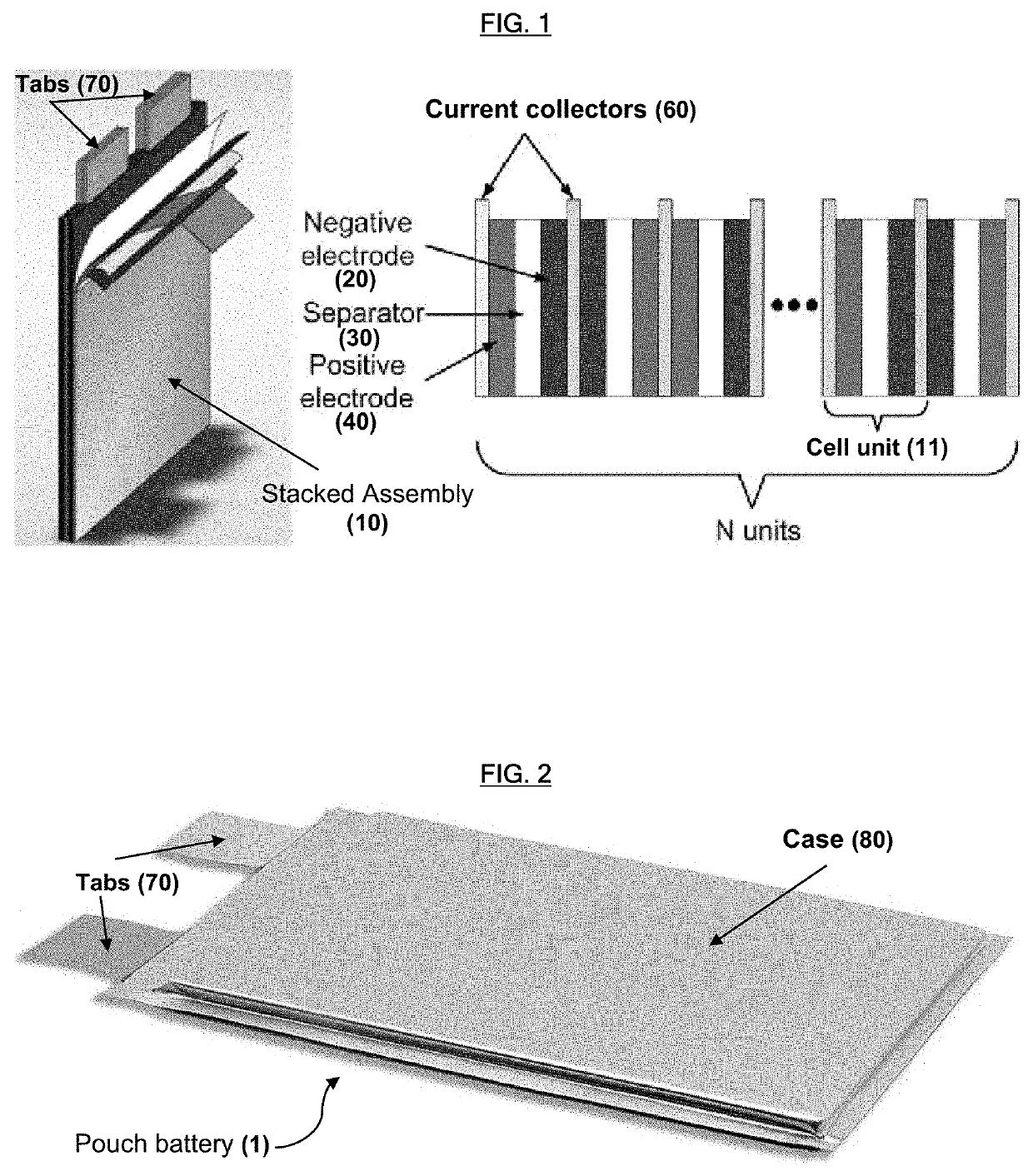
[0149]A pouch primary cell was prepared having the following structure: (1) anode: small particle graphite coated at a thickness of 4 μm on each side of a collector; (2) cathode: an active material layer including NCA, PVDF as a binder, and carbon black as a conductive additive coated on an aluminum foil collector; (3) separator: polyethylene a thickness of 12 μm; (4) stack: 23 cathode plates and 25 anode plates stacked alternately between the separator (the separator being folded in a zig / zag pattern); (5) electrolyte: 1.2 M LiPF6 in a solvent mixture of EC, DMC and EMC (30:40:30 by volume) with 3 wt. % VC as an additive; (6) compression: external compression applied to the stack using springs. The formation condition the pouch cells was C / 10 CC-CV at 60° C. (i.e., C / 10 is the charge rate, which means that it took 10 hours to fully charge; CC stands for constant current; and CV stands for constant voltage. Thus, CC-CV charge means charging at constant current until t...

example 2

Compression: Impedance Vs. SOC

[0152]A pouch primary cell was prepared in the same manner as Example 1.

[0153]A cylindrical primary cell was prepared in a similar manner as Example 1, except that (1) external compression was not applied; (2) the electrode and separator were wound together (instead of stacking the electrode and separator in pouch cells).

[0154]The pouch primary cell was tested at a constant external pressure of about 2 bar using springs, and the cylindrical primary cell were tested without applying any pressure. The results are shown in FIG. 7.

[0155]As shown in FIG. 7, the impedance of the cylindrical primary cell at low state of charge (SOC) was significantly increased due to very low pressure. In contrast, the impedance of the pouch primary cell at low SOC was kept low due to external compression.

example 3

te Additive

[0156]Primary pouch cells were prepared in the manner as Example 1, except for the variations listed in Table 1 below:

TABLE 1C1D1EfficiencyChemistryElectrolyte(Ah)(Ah)(%)Design 1Electrolyte solvent 1 with5.24.382%3 wt. % VC additiveElectrolyte solvent 1 with5.54.275%no additivesDesign 2Electrolyte solvent 2 with5.44.481%3 wt. % VC additiveElectrolyte solvent 2 with6.43.757%no additivesC1 = Charge Capacity;D1 = Discharge Capacity;Solvent 1 = EC / DMC / EMC = 30 / 40 / 30 vol %Solvent 2 = EC / DMC / EMC / MB (methyl butyrate) = 30 / 20 / 30 / 20 vol %

[0157]The test conditions for the experimentation reported in Table 1 were as follows: Charge: C / 10 CC-CV to 4.25V at 25° C. (i.e., C / 10 is the charge rate, which means that it took 10 hours to fully charge; CC stands for constant current; and CV stands for constant voltage. Thus, CC-CV charge means charging at constant current until the max voltage is reached, at which point the charging is switched to constant voltage charge); Discharge: C / 2 CC ...


PUM


Abstract

Provided is pouch battery including an electrode assembly, and a case in which the electrode assembly is sealed and housed; the electrode assembly including a stacked structure of a sheet cathode, a sheet separator, and a sheet anode; the sheet cathode including a positive electrode active material disposed on a current collector; the sheet anode is thin conductive sheet on which lithium metal reversibly deposits on a surface thereof during discharging; the sheet anode being made of a conductive material other than lithium and having a surface substantially free from lithium metal prior to charging the battery. The pouch battery design is flexible and lightweight and provides high power density, making it a suitable replacement for conventional lithium-ion primary batteries and thermal batteries in many applications. Power can be further increased by the application of external compression. Additives and formation conditions can be tailored for forming a solid-electrolyte interface (SEI).

Description

BACKGROUNDTechnical Field[0001]The present disclosure presents a lithium-ion primary pouch battery having an essentially lithium-free design.Description of Related Art[0002]Various types of lithium electrochemical cells in non-aqueous solvents are known in the art. Primary solid cathode lithium cells typically include a lithium anode, an electrolyte prepared from lithium salts dissolved in one or more organic solvent and a cathode containing electrochemically active materials such as transition metal oxides, metal sulfides, fluorinated carbon compounds, etc.[0003]A drawback of such lithium cells arises from the highly reactive nature of lithium metal in air. Lithium readily reacts with water vapor in air. Therefore, lithium anodes must be prepared in an entirely dry atmosphere. The preparation of metallic lithium anodes can be cumbersome, expensive and may also be hazardous.[0004]Another drawback of primary lithium cells is encountered in high-power primary lithium cell designs wher...

Claims


Application Information

Patent Timeline
IPC IPC(8): H01M6/18H01M2/02H01M2/26H01M4/583H01M6/16H01M4/66H01M6/02
CPCH01M6/18H01M2/0207H01M2/0287H01M6/02H01M4/583H01M6/162H01M4/661H01M2/26H01M50/105H01M50/211H01M10/0468H01M6/14H01M50/124H01M10/0481H01M10/044H01M10/0525H01M10/056H01M10/0565Y02E60/10Y02P70/50H01M50/531H01M50/40H01M50/10H01M4/525H01M4/5835
Inventor GRESZLER, THOMASTOKUOKA, SAORI
Owner SAFT AMERICA INC
Why Eureka
Eureka Blog
Learn More