
Three-dimensional graphene antenna and preparation method thereof

a graphene antenna and three-dimensional technology, applied in the direction of resonant antennas, substantially flat resonant elements, chemistry apparatus and processes, etc., can solve the problems of low photoelectric efficiency, high bit error rate, low photoelectric efficiency, etc., to improve the efficiency of electron transmission, improve the specific surface area, and improve the effect of mechanical strength

Pending Publication Date: 2022-02-10
XIAN TECHNOLOGICAL UNIV
View PDF0 Cites 0 Cited by
  • Summary
  • Abstract
  • Description
  • Claims
  • Application Information

AI Technical Summary

Benefits of technology

The present invention provides a three-dimensional graphene antenna and a simple and efficient preparation method. The three-dimensional graphene has a porous structure and is made from a porous material on the basis of two-dimensional graphene. It has lower resistivity, high precision, and good performance, which makes it suitable for various fields such as electronics, information, materials, energy, biomedicine, etc. The preparation method uses pressurized solid particles as a template, which is green and energy-saving. The three-dimensional graphene antenna has low resistivity, high precision, and good use performance, and is easy to operate. It is suitable for specific applications and is efficient and energy-saving.

Problems solved by technology

However, the traditional antenna radiation patches are mostly made of metal, but metal materials have disadvantages such as low photoelectric efficiency, high bit error rate, and non-corrosion resistance.
However, the thickness of single-layer graphene is only 0.35 nm, which is difficult to identify and operate, thereby limiting the practical application of graphene in microstrip antennas.
The traditional preparation method of three-dimensional graphene is not only complicated, but also brings other impurities, which has a certain impact on the physical and chemical properties of the prepared three-dimensional graphene.

Method used


Image

  • Three-dimensional graphene antenna and preparation method thereof
  • Three-dimensional graphene antenna and preparation method thereof

Examples


Embodiment Construction

[0031]In order to make the technical solutions and advantages of the present invention clearer, the present invention will be explained in detail with reference to the drawings and specific embodiments as follows.

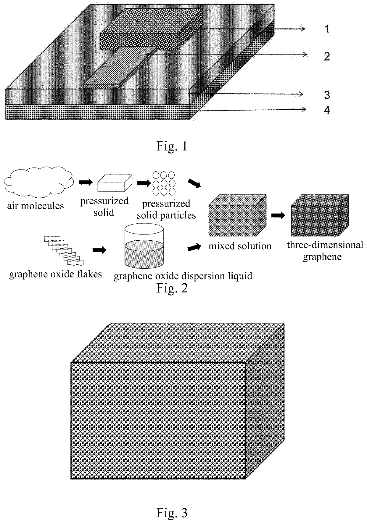
[0032]Referring to FIG. 1, a three-dimensional graphene antenna according to a preferred embodiment of the present invention is illustrated, which comprises a three-dimensional graphene radiation layer 1, a dielectric substrate 3, a metal layer 4 and a feeder line 2, wherein the three-dimensional graphene radiation layer 1 is attached to a top surface of the dielectric substrate 3, the metal layer 4 is attached to a bottom surface of the dielectric substrate 3, the feeder line 2 is provided at one side of the three-dimensional graphene radiation layer 1 and on the dielectric substrate 3 for transmitting radiation field signals formed between the three-dimensional graphene radiation layer 1 and the metal layer 4.

[0033]A preparation method of the three-dimensional graphene an...


PUM

PropertyMeasurementUnit
dielectric constantaaaaaaaaaa
temperatureaaaaaaaaaa
pressureaaaaaaaaaa

Abstract

A three-dimensional graphene antenna includes a three-dimensional graphene radiation layer, a dielectric substrate, a metal layer and a feeder line. The three-dimensional graphene radiation layer is made from porous three-dimensional graphene. A preparation method of the porous three-dimensional graphene includes steps of preparing pressurized solid particles by pressurizing gas into solid micro particles, mixing the pressurized solid particles with a graphene oxide dispersion liquid, removing liquid nitrogen under high pressure and low temperature such that the graphene oxide flakes enwrap around the pressurized solid particles, obtaining a graphene oxide block containing the pressurized solid particles by extruding, sublimating the pressurized solid particles in the graphene oxide block into gas, forming holes in the graphene oxide block and annealing, thereby obtaining the three-dimensional graphene. The three-dimensional graphene has a porous three-dimensional conductive network structure, which is able to be in any shape without any pollution.

Description

CROSS REFERENCE OF RELATED APPLICATION[0001]The present invention claims priority under 35 U.S.C. 119(a-d) to CN 202011641314.1, filed Dec. 31, 2020.BACKGROUND OF THE PRESENT INVENTIONField of Invention[0002]The present invention relates to the field of antenna and low-dimensional material technology, and more particularly to a three-dimensional graphene antenna and a preparation method thereof.Description of Related Arts[0003]In the Internet of Things society, data transmission and reception mainly rely on antennas. As the front-end equipment in the Internet of Things system, the superior performance of the antenna directly affects the whole Internet of Things system. However, the traditional antenna radiation patches are mostly made of metal, but metal materials have disadvantages such as low photoelectric efficiency, high bit error rate, and non-corrosion resistance. If graphene with better performance is used instead of metal, the electrical conductivity, thermal conductivity, a...

Claims


Application Information

Patent Timeline
Patent Type & Authority Applications(United States)
IPC IPC(8): H01Q1/36H01Q1/38C01B32/184C01B32/194
CPCH01Q1/368H01Q1/38C01B2204/24C01B32/194C01B2204/22C01B32/184H01Q9/0414H01Q9/045H01Q9/0407
Inventor LIU, HUANZHAO, JIJIEJIA, JINMEIDU, YUXUANWEN, SHUAIBAI, MINYUXIE, FEIXIE, WANPENGLIU, WEIGUO
Owner XIAN TECHNOLOGICAL UNIV
Learn More