

Pellet Processing Drum
a processing drum and pellet technology, applied in drying machines, lighting and heating apparatus, furnaces, etc., can solve the problems of unsuitable low-value materials processing and typical energy-intensive processes, and achieve the effects of enhancing evaporation, enhancing evaporation, and enhancing water removal
- Summary
- Abstract
- Description
- Claims
- Application Information
AI Technical Summary
Benefits of technology
Problems solved by technology
Method used
Image

Examples
example 1
[0100]A desiccation apparatus in accordance with an embodiment of the present invention was tested to determine the rate of evaporation of water from a sewage sludge feedstock.
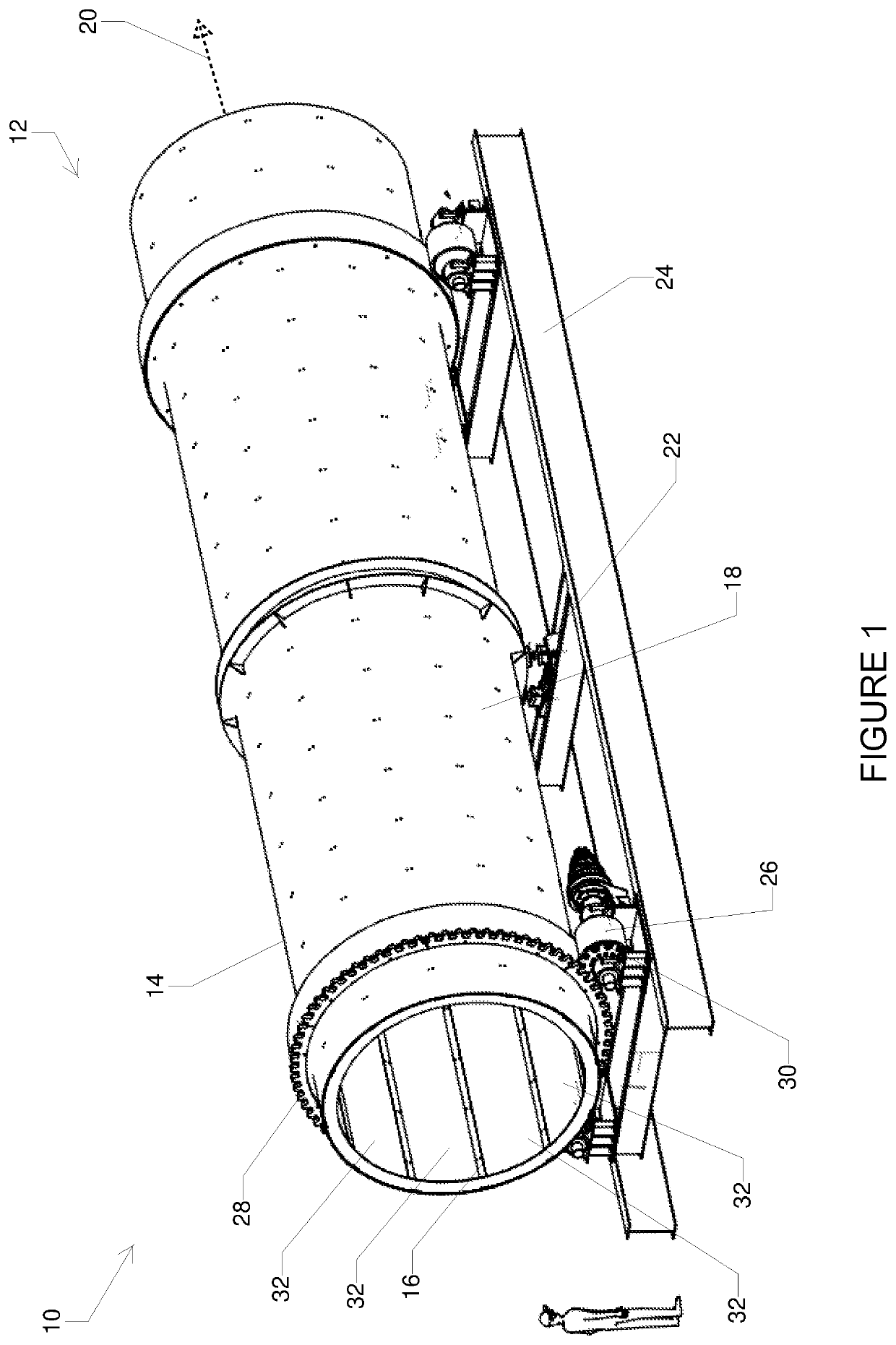
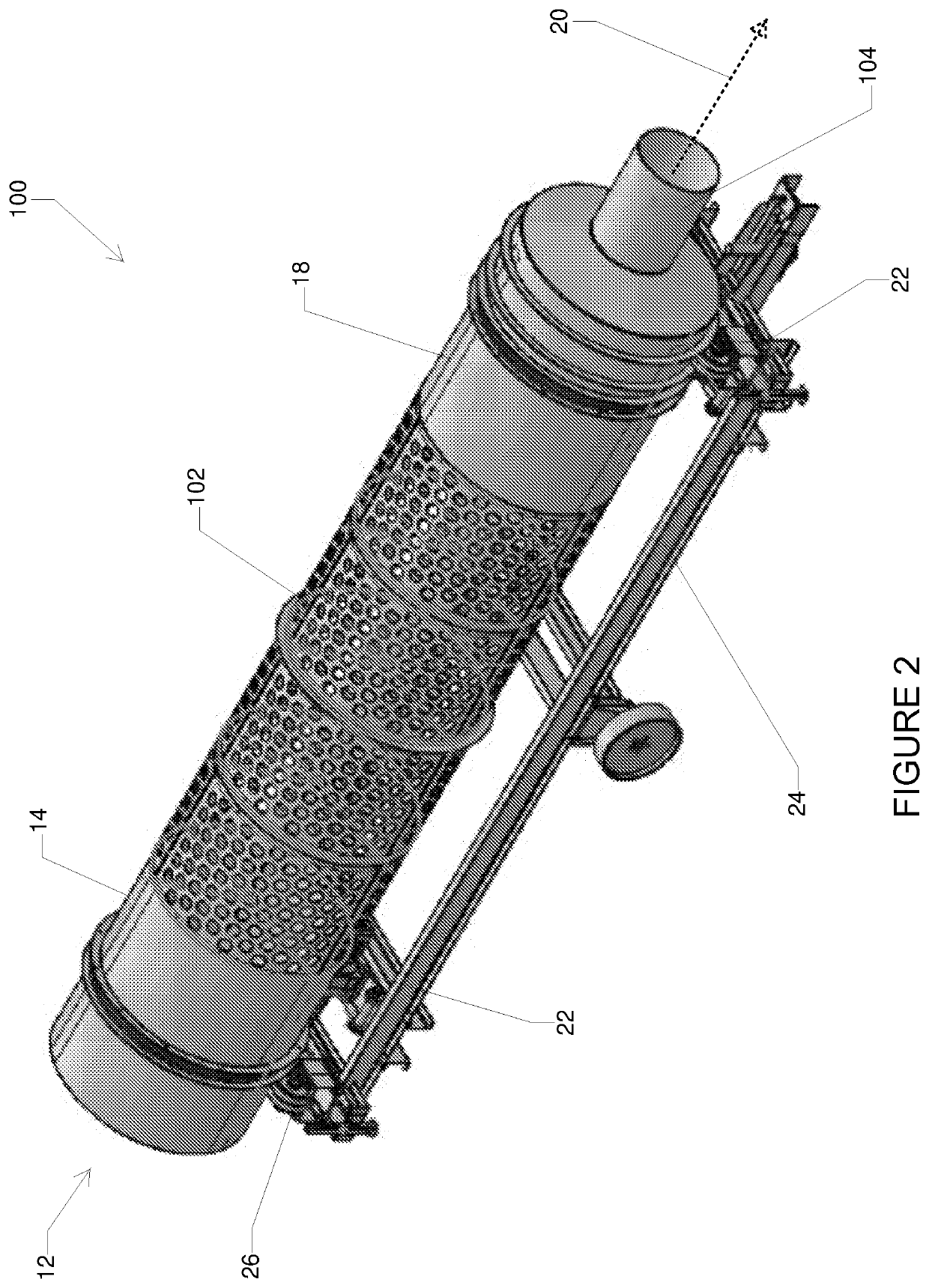
[0101]The desiccation apparatus used had an internal diameter of 1 m and a length of 4 m. The interior surface of the drum was lined with a porous liner constructed from polyethylene fibres. The pore size of the liner was less than 75 μm (AS 3706.7). The thickness of the liner was 6 mm.
[0102]Ambient temperature air was passed through the drum was 8-10 m3 / sec. The drum was rotated as a rate of 2 revolutions per minute and was periodically stopped every 30 seconds to 1 minute for 5 to 10 minutes.
[0103]The water content was periodically measured and the results are shown in Table 1 below.
TABLE 1Water Content MeasurementsAmbientDischargeProductTimeAir TempAmbient AirAir SpeedAir TempDischarge AirWater(days)(° C.)Humidity(km / hr)(° C.)HumidityContent085%1204610115675%2204311125962%3223411125850%4213211135738%5233311...
example 2
[0105]A series of tests were undertaken to determine the effect that different liner materials had on the rates of evaporation.
[0106]Four different lining materials were lined on the interior surface of the desiccation apparatus in accordance with one embodiment of the present invention. The desiccation apparatus used had an internal diameter of 1 m and a length of 4 m. The volume of air passed through the drum was 8 to 10 m3 / sec. The drum was rotated as a rate of 2 revolutions per minute and was periodically stopped every 30 seconds to 1 minute for 5 to 10 minutes.
[0107]Details of the four liners tested are provided in Table 2.
TABLE 2Test CriteriaTrialTest 1Test 2Test 3Test 4Liner MaterialHDPEConveyorPolyethylenePolypropylenePlasticbeltfabricfabricLiner Thickness2 mm8 mm4mm6mmPore size00μmμm(AS 3706.7)Pore size00182μm124μm(ASTM 6767)Coefficient of0048 m / s 10−434 m / s 10−4permeability(AS 3706.9)
[0108]The feed materials had a starting water concentration of 85%. The apparatus was oper...
PUM
 Abstract
Description
Claims
Application Information