Improvements in the welding of pipes

Pending Publication Date: 2022-03-03
SAIPEM SPA
View PDF0 Cites 2 Cited by
  • Summary
  • Abstract
  • Description
  • Claims
  • Application Information

AI Technical Summary

Benefits of technology

The invention relates to a method for welding pipes using high energy welding techniques, such as keyhole welding or electron beam welding. These techniques can create strong welds with low distortion effects. The invention also includes the use of intermediate layers to mitigate against rapid cooling rates after the heating energy is removed. The welds can be performed in one-pass, which allows for faster welding and reduces the need for robotic weld jigs. The method can also involve multiple welding heads or torches working on different sectors of the pipe circumference or both sides of the pipe. The thickness of the material between the end faces of the pipes can be greater than 0.05 mm, with a preferred range of 0.1 mm to 2 mm. The invention provides a faster and more efficient way to weld pipes, resulting in stronger and more stable welds.

Problems solved by technology

In the oil and gas services industry, one of the main costs of any project is the time spent at sea.
One of the main rate limiting steps, determining how long the pipe laying vessel must remain at sea, is the process of forming the pipeline in the firing line as described above.
Whilst GMAW technology is well understood and produces high quality weld joins, one of its main disadvantages is that several welding passes are required in order to maintain form a joint of a thick section of pipe.
However, in such applications that require thick-section welding, challenges remain yet in developing high energy welding techniques to compete with conventional welding methods.
The disadvantages of high energy welding technologies (such as laser welding or electron beam welding) include the safety associated with the high energy beam, and the need to control any plasma effects which occur during the welding process.
However, this prior art, whilst disclosing a method which may improve the quality of the weld join, has also disclosed something which adds complexity and possibly a longer time on the weld firing line.
This piece of prior art may reduce the penetration depth of the welding source, reducing the thickness of the pipes which may be welded with this technology, a major disadvantage.
A typical problem of laser welding is of metallurgical type and it is caused by the high cooling rate of the material involved in the welding.
This can cause defects in the welded material: the laser brings heat on a low volume of material with a high thermal power in a very short period of time.
Consequently, unwanted mechanical characteristics, such as low toughness and resilience and / or surface defects can form.
High cooling rates can also induce adverse grain growth paths during solidification process often resulting in solidification defects or other defects that are formed when the material is at a high temperature and then rapidly cools.
The formation of such hot cracks, or solidification cracks, is a common issue in high energy welding followed by rapid cooling of the metal, once the heating energy is removed.
However, this piece of prior art has clear disadvantage, in that the consumable wire used can only penetrate so far into the thickness of the pipe, putting an upper limit in the thickness of the pipes that this can be used on at under 10 mm in thickness.
An issue with using prefabricated rings is that there are many different combinations of pipe joint during assembly and misalignment between the parts to be joined, which make it impracticable have a consumable ring available for every possible joint.
Ensuring a good and accurate fit between each pipe end face and opposing side of the prefabricated ring is another potential disadvantage of this proposed solution.

Method used


Image

  • Improvements in the welding of pipes
  • Improvements in the welding of pipes
  • Improvements in the welding of pipes

Examples


first embodiment

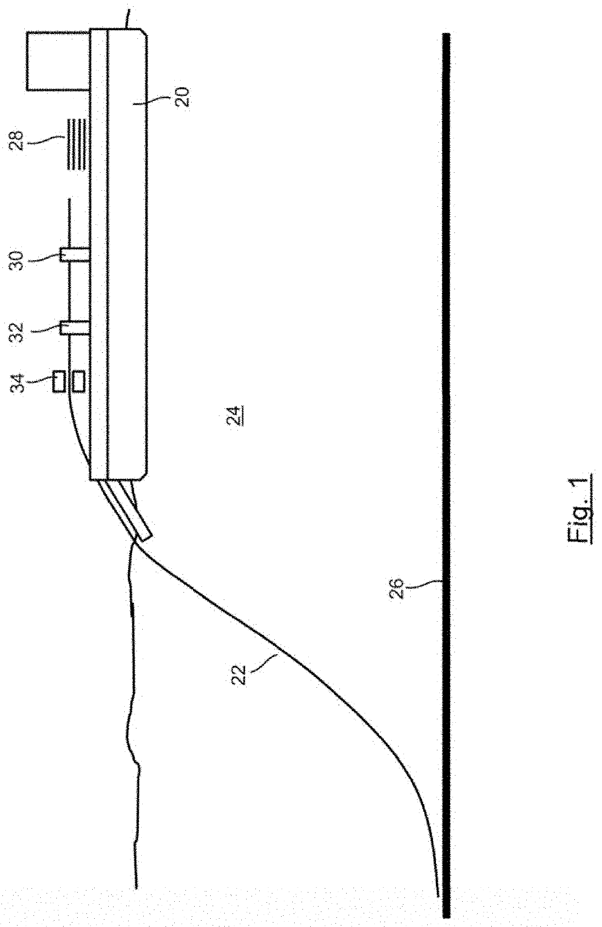
[0079]FIG. 1 shows a pipe laying vessel 20 laying a pipeline 22 in water 24 using an S-lay process. It will be seen that the pipeline 22 forms the general shape of an “S” as it is laid off the vessel 20 towards the seabed 26. The first embodiment concerns welding successive sections 28 of pipe to the end of the pipeline 22 as the pipeline is laid from the vessel 20.

[0080]The sections 28 of pipe added to the pipeline 22 (string) are each 12 m long (but could be multiples of 12 m in other embodiments, or any other length). Each pipe has an outer diameter of 1000 mm. The sections 28 of pipe (and the resulting pipeline) are steel pipes having a relatively low carbon content. The steel is low carbon weldable grade steel having a relatively low effective carbon content (CE).

[0081]The alloying composition of the steel pipe in this embodiment (as ascertained using the ASTM E415-17 “standard test method for analysis of carbon and low-alloy steel by spark atomic emission spectrometry” made av...

third embodiment

[0098]the invention is illustrated by FIGS. 13 and 14. In this embodiment, the intermediate material 61 is deposited on the ends 60 of the pipes as a porous material having multiple voids formed therein. Such voids may comprise at least some that are in fluid communication with each other. Such voids may comprise at least some that are closed voids. In this embodiment of the invention, the coating of the pipes performed in a factory on land. The intermediate material 61 is deposited as a lattice-type material having voids 68 that collapse as the surrounding material deforms when the pipe ends are brought together. Such voids 68 are evenly distributed to ensure an even distribution of the filler material between the faces of the ends 60 of the pipes when fully brought together. This may assist in accommodating for misalignment in the axial and radial direction of the pipe end faces. Each of the voids may have a volume of between 0.001 mm3 and 1 mm3. There may therefore be thousands o...

fourth embodiment

[0099]FIG. 15 illustrated the invention, which incorporates the features of previous embodiments, except that the intermediate material is not coated on either of the ends 60 of the pipes. Instead, it is provided as a thin layered gasket 63 which in use is inserted between the pipes, mechanically by a device 64, as the two pipes are brought together. This has the benefit that the pipes do not have to be pre-coated before welding. The gasket 63 is made of material that is softer than the pipe material and is thus able to deform in the manner described above to reduce the effects of misalignment of the pipe end faces.

[0100]A fifth embodiment of the invention, not separately illustrated, incorporates the features of the first embodiment, except that the intermediate material is substantially entirely nickel (purity >99%), and is applied at a minimal thickness, 0.1 mm on one pipe end face only meaning that the total thickness of filler material sandwiched between the pipe end faces is 0...


PUM

PropertyMeasurementUnit
Lengthaaaaaaaaaa
Lengthaaaaaaaaaa
Fractionaaaaaaaaaa

Abstract

A first metal pipe is welded to a second metal pipe in a method of laying pipeline, for example from a pipe-laying vessel at sea. The metal pipes may have an outer diameter greater than 150 mm and a pipe wall thickness of greater than 15 mm. The first pipe and the second pipe are brought together prior to welding so as to sandwich a third type of metal material between the pipe ends. The thickness of the third type of material, immediately before welding may be between 0.05 mm and 2 mm. The third metal material is melted together with the metal material of the first pipe and the second pipe.

Description

FIELD OF THE INVENTION[0001]The present invention concerns methods and apparatuses relating to pipe welding. More particularly, but not exclusively, this invention concerns the welding of pipes end-to-end, with a high energy welding apparatus, which induces high temperatures in the weld material and consequent rapid cooling in the weld joint and / or surrounding material, yet produces high quality welds for pipes that are suitable for use for conveying oil and / or gas.BACKGROUND OF THE INVENTION[0002]Pipelines for the transportation of oil and gas must often be laid in water, for example at sea. Typically, when laying a pipeline at sea, one end of the pipeline (sometimes referred to as the string) is held by a pipeline laying vessel and a section of pipe is welded onto the end of the pipeline, at a location on the vessel commonly referred to as the firing line. In the oil and gas services industry, one of the main costs of any project is the time spent at sea. One of the main rate limi...

Claims


Application Information

Patent Timeline
IPC IPC(8): B23K26/211B23K26/282B23K26/342
CPCB23K26/211B23K2101/06B23K26/342B23K26/282B23K2101/10B23K2103/04
Inventor STEFANO, GIORGIOROSSIN, DAVIDE
Owner SAIPEM SPA
Why Eureka
Try Eureka