Modular flow cytometry systems and methods of processing samples

a flow cytometry and module technology, applied in the field of modules of flow cytometry systems and methods for processing samples, can solve the problems of sample mishandling, contamination, overall error, and increased likelihood of incorrect system parameters or calibration, and existing systems and methods which rely primarily on human operators, and process are also subject to extended downtime and lengthy set-up and calibration steps

Pending Publication Date: 2022-05-26
ABS GLOBAL
View PDF0 Cites 3 Cited by
  • Summary
  • Abstract
  • Description
  • Claims
  • Application Information

AI Technical Summary

Benefits of technology

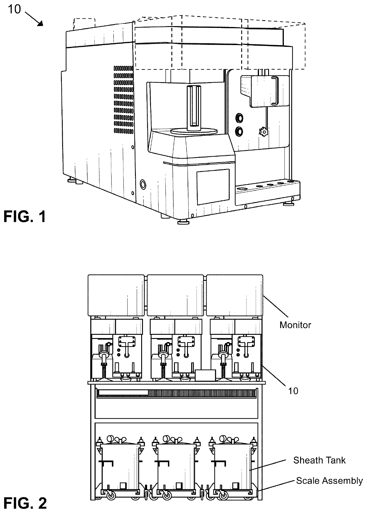
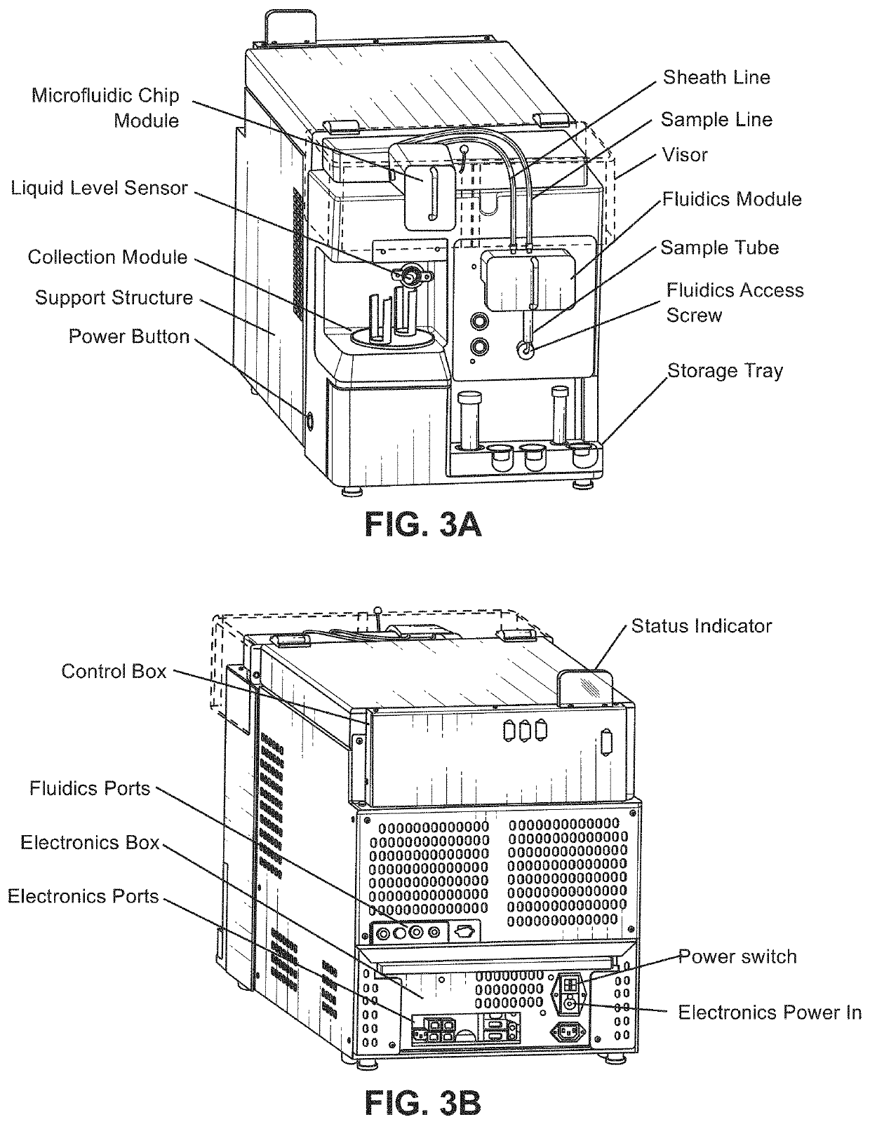
[0027]In some embodiments, the present invention features a modular flow cytometry system for sexing a sample. The system may comprise a chassis sectioned into a plurality of levels; an electronics module disposed in the first level of the chassis, the first level being the lowest of the plurality of levels, wherein the electronics module includes one or more computer processors and a plurality of electronic ports; a sample pathway module disposed in the second level of the chassis, wherein the sample pathway module includes a microfluidic module for holding a microfluidic chip; a fluidics module disposed in the second level of the chassis, wherein the fluidics module is fluidically coupled to the sample pathway module for circulating one or more fluids through the sample pathway module; an interrogation module disposed in the third level of the chassis and operatively coupled to the electronics module, the interrogation module including a detection laser operatively coupled to a detection assembly, and a kill laser operatively coupled to the detection assembly for processing a sample flowing through the microfluidic chip, wherein the kill laser and the detection laser are disposed on a common side of the interrogation module with respect to each other; and a sample mixing and collection module disposed below the microfluidic module in the same second level of the chassis, the sample mixing and collection module configured to collect and automatically mix the processed sample exiting the microfluidic chip. The sample mixing and collection module rotates about a pivot so as to move in an arcuate path, which allows for mixing of the sample in a uniform and controlled motion. Each module can be disposed in the support structure, and configured to be separately removed from the support structure and re-installed or replaced with another of the same module for near-continuous operation of the modular flow cytometry system.
[0094]In further embodiments, the present invention provides a method for producing a sexed, non-human semen product. The method may comprise processing a semen sample in a flow cytometry apparatus to select a first sub-population of the sample comprising at least one desirable characteristic from a second sub-population of the sample comprising at least one non-desirable characteristic, collecting the sample primarily comprising the first sub-population comprising the at least one desirable characteristic in a sample collection container, and automatically mixing the collected sample in the sample collection container using any one of the sample mixing systems described herein. Mixing the collected sample may be based on a set of defined sample mixing parameters associated with the processed sample, such as one or more of a mixing arc defined in degrees, a mixing arc defined in steps, and a rotational speed. The sample mixing system can rotate about a pivot so as to move in an arcuate path, which allows for mixing of the sample in a uniform and controlled motion.

Problems solved by technology

The extensive use of operator intervention, calibration, and operation in flow cytometry increases the likelihood of incorrect system parameters or calibration, sample mishandling, contamination, and overall error.
Existing systems and methods which rely primarily on human operators in all aspects of the process are also subject to extended downtime and lengthy set-up and calibration steps based on the extensive expert manual intervention required.
However, none of the existing systems completely isolate a sample pathway used by a fluid sample from the flow cytometry or microfluidic analysis device.
For example, while in existing systems a portion of the sample pathway, such as a microfluidic chip or cassette, may be removed, other portions of the sample pathway contacted by a fluid sample are part of the flow cytometry device itself and cannot be removed from the system.
Elimination of cross-contamination is necessary where the samples comprise different genetic material or traits and where contamination would render the samples unsuitable for use.
An additional problem with existing systems and methods is that while portions of the system may be removed for cleaning, the cleaning process itself is labor intensive and may require extensive manual input and configuration.
However, many systems treat components such as microfluidic chips, cartridges, or cassettes as disposable, single-use items which greatly increases the amount of single-use plastic or glass waste by the lab.
There are advantages and disadvantages to using either a sorting decision or a destruction decision to process particles in flow cytometry.
A sorting decision process or method may cause undue stress on the selected or desirable sperm cells, reducing viability or fertility of a collected sample of sperm cells.
A destruction decision process or method may leave sperm cells that have not been completely deactivated in a collected sample, reducing the viability or fertility potential of the overall sample.
In a destruction decision, which may include an inactivation or damaging of the particle, certain particles having certain fluorescence characteristics, comprising certain properties, or meeting certain thresholds as detected by one or more detectors may be damaged or deactivated.
This destruction may include ablation or photo-damaging by a directed and focused emission of electromagnetic radiation by a laser.
Additionally, with respect to destruction decision processes, aligning a laser or other electromagnetic radiation emission device used in the destruction process is a particularly time consuming process that requires extensive training and expertise to perform properly.
This issue is particularly prevalent when changing between sample batches for a particular particle, such as when changing between unprocessed sperm samples from different male animals in semen processing.
These existing systems may require complex, time-consuming, and precise setup and configuration to function properly.
If set up incorrectly, these existing systems may not function as desired, if at all.
The multiple optical pathways may also cause problems with crosstalk and interference between separate optical systems.
This process results in several forms of errors, ranging from interpretation of what qualifies as a gentle swirl, variances from operator to operator in achieving mixing every five minutes, and the removal of the tube out of the path of the sample, e.g. cells, or causing sample to splash out of the tube due to over-mixing.
One is that they can take up space if they are too tall to fit underneath a dispensing instrument.
However, these solutions may cause stress to the cells.
Existing cytometer systems are large, bulky, and non-modular.
Once assembled, the components are integrated onto the instrument itself and cannot be individually removed or repaired without extensive disassembly of the entire device or table of devices.
These systems are intricate and complicated, and are not conducive to field repairs or calibration by relatively unskilled technicians.
Additionally, these systems require prolonged downtime for maintenance, repairs, or cleaning, resulting in hours of interruption or longer if a skilled technician is unavailable.

Method used


Image

  • Modular flow cytometry systems and methods of processing samples
  • Modular flow cytometry systems and methods of processing samples
  • Modular flow cytometry systems and methods of processing samples

Examples


example 1

[0299]Without wishing to limit the present invention to a particular application or embodiment, the following exemplary embodiment is provided.

[0300]A flow cytometry particle sorting system comprises a detection laser assembly, a microfluidic ship, a detection sensor, a set of signal processing electronics, a graphical user interface, a CCD camera, a kill laser module, and a kill sensor. The detection laser assembly is configured to excite a dye, such as a Hoechst dye, within a particle, which may be an individual sperm cell. The beam from the detection laser is focused to a specific size, such as an elliptical shape having a fast axis of 3.5-20 μm and a slow axis of 30-150 μm. The microfluidic chip accepts a particle sample, such as an ejaculate sample comprising sperm, and focuses or orients the particles using a sheath fluid within one or more microchannels in the chip. The detection sensor collects light emission at the detection laser location. The signal processing electronics...

example 2

[0304]Without wishing to limit the present invention to a particular application or embodiment, the following exemplary embodiment is provided.

[0305]Typically, pulsed lasers are used for fluorescing dye in a particle in a flow cytometry system. For example, existing systems for semen sexing in sperm may use pulsed lasers to fluoresce a Hoechst dye, such as Hoechst 33324, in a sperm cell to determine an amount, and therefore type, of DNA in a sperm cell in a sexing process. However, using a CW laser provides benefits in efficiency, calibration, and setup compared to traditional pulsed lasers. The use of CW lasers in the present invention provides said improvements over existing pulsed detection lasers and detection laser assemblies while maintaining the same fertility or viability of sperm cells sorted in this manner within a statistically significant margin of error. The conception rate as a measurement of fertility for cells irradiated by a CW laser was at least as good as, if not ...

example 3

[0306]Without wishing to limit the present invention to a particular application or embodiment, the following exemplary embodiment is provided.

[0307]A laser-based particle detection and deactivation system comprises a kill laser assembly and a detection laser assembly. The kill laser assembly may operate at a power of 350 mW to 2 W. The power of the detection laser assembly may be set from 10 mW to 50 mW. Power delivered by the detection laser assembly can incur a power loss of approximately 10% and a measured power drift over a 24-hour period of less than + / −1%. Accurate and steady detection laser power may be achieved by increasing laser power over a first minute of operation and lowering laser power thereafter to provide for stable detection power with an increased temperature of approximately 4 degrees Celsius.

[0308]With reference now to FIG. 29A and FIG. 29B, respective views of representative graphical user interface outputs measuring a detection laser beam size and intensity ...


PUM

PropertyMeasurementUnit
widthaaaaaaaaaa
widthaaaaaaaaaa
widthaaaaaaaaaa

Abstract

Modular flow cytometry systems and methods for processing samples are described herein. The systems include automated or semi-automated modules that are replaceable and removable. A sample pathway module may be removed and placed in a microfluidic device cleaning module for cleaning, and then reinstalled or stored for later use. The systems further include optical modules, electronics modules, and mixing and collection modules. The optical module includes a photo-damaging assembly and detection laser assembly that may be on the same side relative to a plane or surface of a flow cytometry device and opposite of a detection assembly. The laser beam may have a beam waist that is wider in a direction perpendicular to a flow direction than in the flow direction. The mixing and collection module can automatically mix a sample being collected in a sample tube and switch to another sample tube when the other tube is full.

Description

CROSS-REFERENCES TO RELATED APPLICATIONS[0001]This application is non-provisional and claims benefit of U.S. Provisional Application No. 63 / 230,568 filed Aug. 6, 2021, U.S. Provisional Application No. 63 / 162,222, filed Mar. 17, 2021, U.S. Provisional Application No. 63 / 119,769, filed Dec. 1, 2020, and U.S. Provisional Application No. 63 / 117,104 filed Nov. 23, 2020, the specifications of which are incorporated herein in their entirety by reference.[0002]The present application incorporates by reference U.S. Design patent application Ser. No. ______, filed Nov. _, 2021, entitled MODULAR CYTOMETER SYSTEM (Klas et al.), under docket no. DS-38-2021-DS1, and PCT App. No. ______, filed Nov. _, 2021, entitled MODULAR FLOW CYTOMETRY SYSTEMS AND METHODS OF PROCESSING SAMPLES (Klas et al.), under docket no. GS-38-2021-WO1 herein in their entirety.FIELD OF THE INVENTION[0003]The present invention relates to automated and semi-automated systems and methods for processing samples. More specifical...

Claims


Application Information

Patent Timeline
Patent Type & Authority Applications(United States)
IPC IPC(8): G01N15/14B01L3/00
CPCG01N15/1404G01N2015/1006B01L3/502761G01N15/1484G01N2015/149G01N15/1459B01L2200/10B01L2200/028B01L2200/0652
Inventor KLAS, GARYMCADA, DANIELXIA, ZHENGEBERSOLE, MATTHEWLENA, BRIANAPPLEYARD, DAVIDLU, RICHARDBUCKLEY, SCOTTABERMOSKE, MARK
Owner ABS GLOBAL
Why Eureka
Try Eureka