Electromagnetic cavity able to support tamm modes

a technology of electromagnetic cavity and electromagnetic cavity, which is applied in the field of electromagnetic cavity of tamm, can solve the problems of unfavorable diffraction limit, low quality factor, and substantial drawback of thz component production

Pending Publication Date: 2022-08-04
CENT NAT DE LA RECHERCHE SCI +4
View PDF0 Cites 2 Cited by
  • Summary
  • Abstract
  • Description
  • Claims
  • Application Information

AI Technical Summary

Problems solved by technology

However, these electronic resonators possess a low quality factor (typically 10 at room temperature) this being a substantial drawback for the production of many THz components.
This diffraction limit is unfavorable to a substantial interaction of the modes of the optical resonator with active or passive elements of small sizes.
Thus, it is very difficult to efficiently couple elements of characteristic size of a few tens of microns to the modes of conventional optical resonators at THz frequencies.
In addition, the resonant frequency of these optical cavities can be adjusted only via the effective length of the resonator, and the profile of the modes is difficult to control or modify.

Method used


Image

  • Electromagnetic cavity able to support tamm modes
  • Electromagnetic cavity able to support tamm modes
  • Electromagnetic cavity able to support tamm modes

Examples


first embodiment

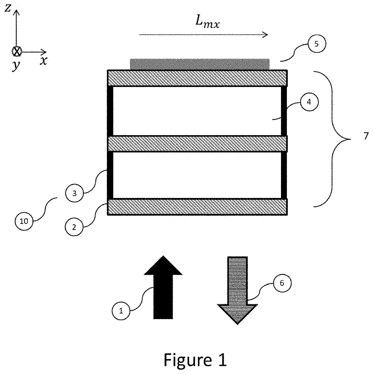
[0045]The invention is based on a Tamm resonator suitable for the THz spectral range. FIG. 1 shows a schematic profile view of a Tamm electromagnetic THz cavity 10 according to the invention. In this embodiment, the cavity is formed from a periodic stack 7 and from a metal layer 5. The periodic stack 7 comprises an alternation, in a z-direction, of dielectric or semiconductor layers of high and low refractive index forming an interference mirror or DBR (distributed Bragg reflector), and having an upper layer of high refractive index. By low and high refractive index, what is meant is that the refractive index that is said to be high is higher than the refractive index that is said to be low. The stack reflects a certain wavelength range (called the band gap) in the spectral range of the incident THz radiation 1 propagating in the z-direction. The thickness of each of the layers is equal to about an uneven multiple of λ / 4n (n refractive index in the layer), A being the central wavele...

second embodiment

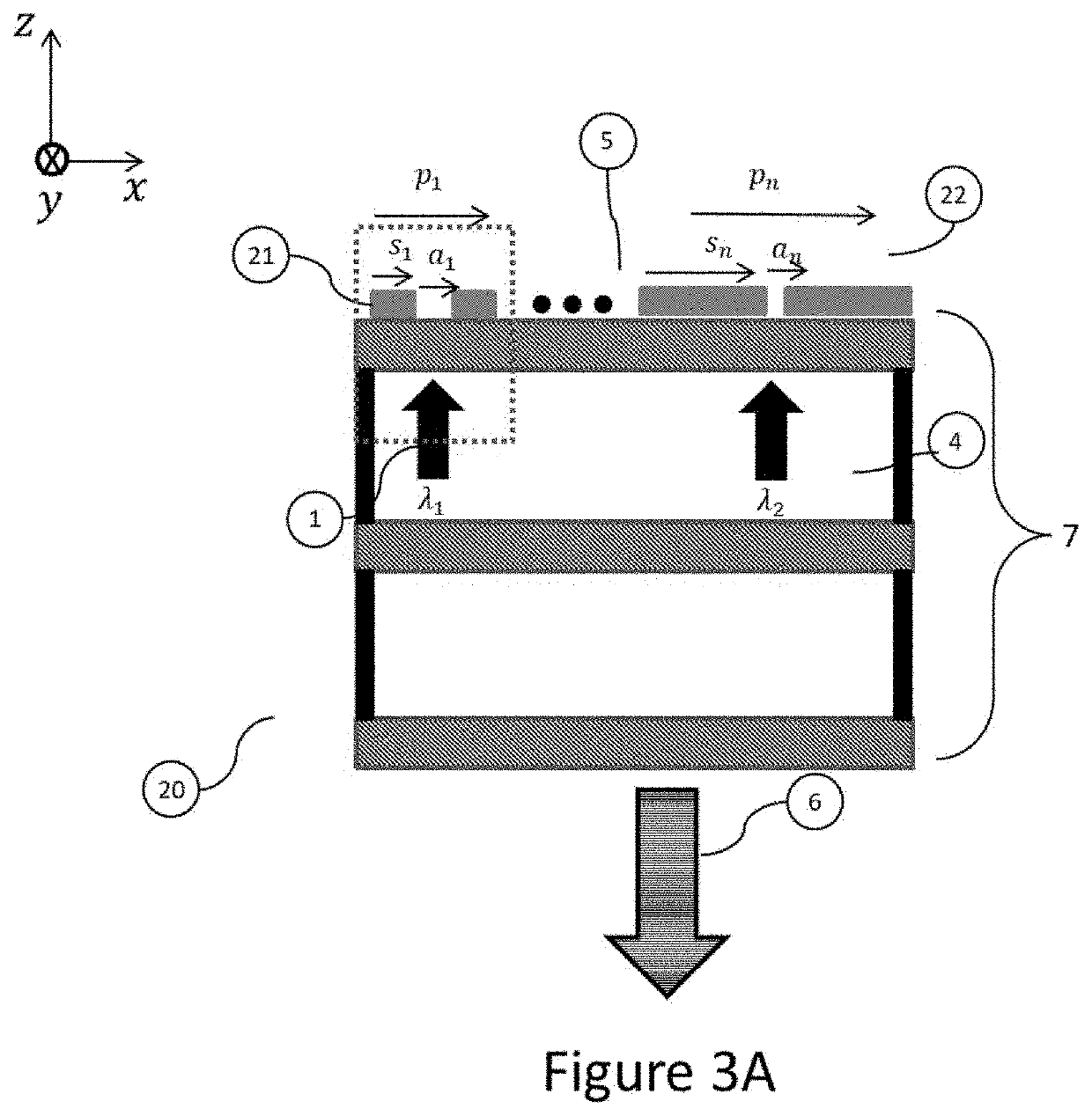
[0055]FIG. 3A illustrates a schematic profile view of a Tamm electromagnetic THz cavity 20 according to the invention. In this embodiment, the DBR is identical to that of the cavity 10 but the upper metal layer 5 is discontinuous. It is structured so as to form a grating of metal strips of width s and separated by a distance a and of fill factor ff=s / p with p=s+a. It is known that the resonant frequency of the cavity 20 and the quality factor of the cavity 20 decrease as the fill factor decreases.

[0056]FIG. 4A and FIG. 4B show the variation in the resonant frequency and in the quality factor as a function of the fill factor of the Tamm cavity 20, respectively, in the case where the upper metal layer is structured so that the fill factor is constant in the x-direction. Here, the periodicity p of the Tamm cavity is set and equal to 75 μm, whereas the width s of the metal strips varies with ff. It may be seen that resonant frequency and quality factor increase with fill factor. It is t...

third embodiment

[0067]In order to obtain a THz cavity the resonant frequency of which is tunable, while maintaining a high quality factor, the cavity 30 of the invention, which is schematically shown in profile in FIG. 5, comprises a mirror 31. This mirror 31 is composed of a lower metal layer 32 and a carrier layer 33. In the embodiment of FIG. 5, the assembly 20 formed by the DBR 7 and the upper metal layer 5 is identical to that of FIG. 3A and the lower metal layer 32 of the mirror 31 is made of gold and the upper carrier layer 33 of the mirror 31 is made of silicon. The mirror 31 is placed above the upper metal layer 5 at a distance D=λm / 4 from the latter in order to maximize the strength of the electric field in the upper metal layer and in the region below the upper dielectric layer of the stack 7. The mirror is separated from the layer by a dielectric layer 34. In the example of FIG. 5, this layer is a layer of air. Here, λm corresponds to the longest resonant length of the cavity 30, i.e. t...


PUM

PropertyMeasurementUnit
sizeaaaaaaaaaa
sizeaaaaaaaaaa
sizeaaaaaaaaaa

Abstract

A Tamm electromagnetic cavity (10, 20, 30, 40, 60) possessing a resonant frequency in the THz domain, comprising:
    • an interference mirror that is reflective in the THz domain, this mirror consisting of a stack of dielectric layers (7) comprising an alternation, in a z-direction, of two different layers, a layer referred to as the layer of high refractive index (2) and a layer referred to as the layer of low refractive index (4), the index of the layer of low refraction being lower than that of the layer of high refractive index, and being manufactured by stacking layers mechanically or by joining dielectric layers to one another;
    • an upper metal layer (5) deposited on or added to an upper dielectric layer of said interference mirror so as to form a structure that supports at least one Tamm mode in the THz domain, the upper metal layer (5) being structured so as to form an antenna possessing a resonant frequency equal to that of the electromagnetic cavity.

Description

TECHNICAL FIELD[0001]The present invention relates to a Tamm electromagnetic cavity possessing at least one terahertz (THz) resonant frequency.PRIOR ART[0002]Below, a resonant cavity possessing at least one resonant frequency in the typical range of 0.1 THz to 10 THz will be referred to as a THz cavity. THz cavities are used for the development of many passive and active components such as THz radiation sources, detectors, sensors, modulators and filters. In addition, these cavities are essential to THz devices aiming to achieve strong radiation-matter coupling. THz cavities also allow the sensitivity of spectroscopy systems to be improved by making it possible to greatly increase the length of interaction between the absorbent medium and the radiation. Current THz cavities may be split into two main categories: optical resonators and electronic resonators.[0003]Electronic resonators are based on metal structures allowing very sub-wavelength confinement of radiation, because propaga...

Claims


Application Information

Patent Timeline
Patent Type & Authority Applications(United States)
IPC IPC(8): G02B5/08G02F1/01
CPCG02B5/0866G02F2203/13G02F2203/10G02F1/0102G02B5/008G02F1/01
Inventor MANGENEY, JULIETTEDHILLON, SUKHDEEPSYMONDS, CLÉMENTINEBELLESSA, JOËLMESSELOT, SIMON
Owner CENT NAT DE LA RECHERCHE SCI
Why Eureka
Try Eureka