High Emissivity Cerium Oxide Coating

a cerium oxide and high emissivity technology, applied in the direction of coatings, etc., can solve the problems of resting to melt, tolerating temperatures of 1100° c. or lower,

Pending Publication Date: 2022-08-11
SCG CHEM CO LTD
View PDF0 Cites 5 Cited by
  • Summary
  • Abstract
  • Description
  • Claims
  • Application Information

AI Technical Summary

Problems solved by technology

Conventionally, chromium oxide is used as a high emissivity coating in a steam cracking furnace, but it can only tolerate temperatures of 1100° C. or lower.
Above this temperature, the high vapor pressure of chromium causes the coating material to become unstable and start to disintegrate, causing the rest to melt.

Method used


Image

  • High Emissivity Cerium Oxide Coating

Examples


example 2

[0129]A mixture of 84.3 wt % cerium oxide (CeO2) powder and 15.7 wt % iron oxide (Fe2O3) (i.e. an atomic ratio of 1:0.2) was prepared, wherein the wt % values are based upon the total weight of the mixture. The mixed composition was grinded and mixed by ball milling. Then, the ball was removed and the composition was dried at 110° C. overnight to obtain the mixed composition in powder.

[0130]A coating solution was prepared by mixing 50 wt % of the powder with 50 wt % of an aqueous aluminium phosphate solution containing 50% v / v aluminium phosphate.

[0131]The Fe2O3-doped cerium oxide coating solution was directly sprayed to 300 μm thickness on a primer-coated substrate prepared according to the Preparatory Example. The coating specimen was then sintered for 3 hr at 1200° C. with heating rate of 1° C. / min.

[0132]The emissivity of the coated substrate was measured according to the method described above.

[0133]The Fe2O3-doped CeO2 coating was found to show an increased emissivity with incr...

example 3

[0134]A mixture of 92.0 wt % cerium oxide powder and 8.0 wt % cobalt oxide (CoO) (i.e. an atomic ratio of 1:0.2) was prepared, wherein the wt % values are based upon the total weight of the mixture. The mixed composition was grinded and mixed by ball milling. Then, the ball was removed and the composition was dried at 110° C. overnight to obtain the mixed composition in powder.

[0135]A coating solution was prepared by mixing 50 wt % of the powder with 50 wt % of an aqueous aluminium phosphate solution containing 50% v / v aluminium phosphate.

[0136]The CoO-doped cerium oxide coating solution was directly sprayed to 300 μm thickness on a non-coated substrate. The coating specimen was then sintered for 3 hr at 1200° C. with heating rate of 1° C. / min.

[0137]The emissivity of the coated substrate was measured according to the method described above.

[0138]The emissivity of the CoO-doped CeO2 coating at 900° C. increased by 50% based on the emissivity at 600° C. and reached a saturation value ...
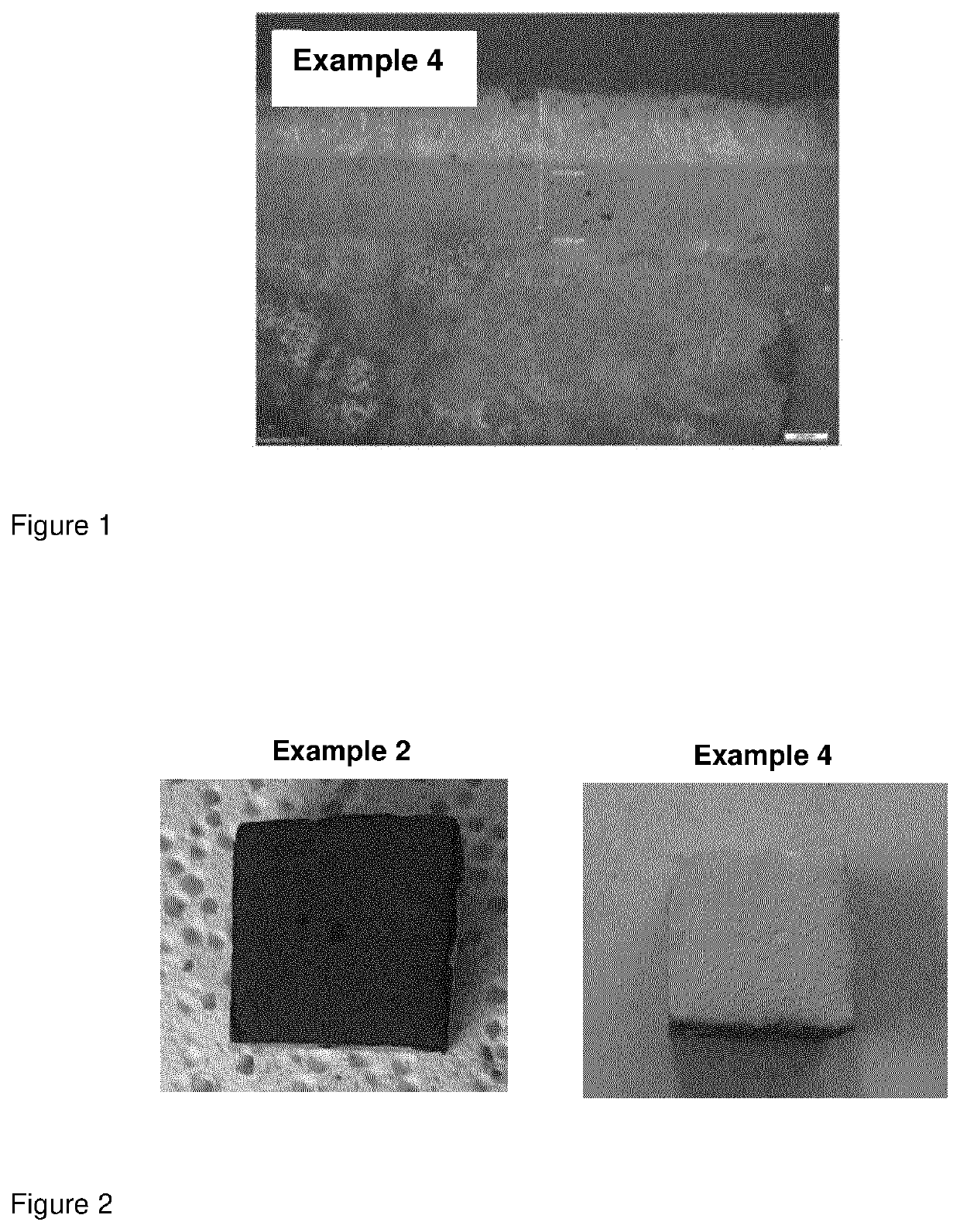
example 4

[0139]A mixture of 72.5 wt % cerium oxide (CeO2) powder and 27.5 wt % lanthanum oxide (La2O3) (i.e. an atomic ratio of 1:0.2) was prepared, wherein the wt % values are based upon the total weight of the mixture. The mixed composition was grinded and mixed by ball milling. Then, the ball was removed and the composition was dried at 110° C. overnight to obtain the mixed composition in powder.

[0140]A coating solution was prepared by mixing 50 wt % of the powder with 50 wt % of an aqueous aluminium phosphate solution containing 50% v / v aluminium phosphate.

[0141]The La2O3-doped cerium oxide coating solution was directly sprayed to 300 μm thickness on a primer-coated substrate prepared according to the Preparatory Example. The coating specimen was then sintered for 3 hr at 1200° C. with heating rate of 1° C. / min.

[0142]The appearance of all Examples was checked after sintering and in all cases it was found that the coating appeared dense and without cracks on the surface.


PUM

PropertyMeasurementUnit
wavelengthaaaaaaaaaa
emissivityaaaaaaaaaa
temperatureaaaaaaaaaa

Abstract

The present invention relates to a coating composition comprising: 10 to 80 wt % of cerium oxide comprising a dopant based upon the total weight of the composition, wherein said dopant is selected from iron oxide, cobalt oxide, chromium oxide, lanthanum oxide, or mixtures thereof, and the atomic ratio of dopant metal to cerium is in the range 0.01:1 to 0.5:1; and 10 to 50 wt % of binder based upon the total weight of the composition.

Description

FIELD OF THE INVENTION[0001]The present invention relates to a coating composition (e.g. a high emissivity coating composition), a kit and a method for making the composition, a method for coating substrates with the composition, and a substrate coated with the composition.BACKGROUND OF THE INVENTION[0002]High emissivity coatings can be used to reduce energy and production costs in a petrochemical furnace. The high emissivity material is used to cover the inner surface of the furnace wall, enabling it to absorb and re-emit heat and thereby increase thermal efficiency. Conventionally, chromium oxide is used as a high emissivity coating in a steam cracking furnace, but it can only tolerate temperatures of 1100° C. or lower. Above this temperature, the high vapor pressure of chromium causes the coating material to become unstable and start to disintegrate, causing the rest to melt.[0003]Cerium oxide is a rare earth based material which is chemically stable and has a good thermal resist...

Claims


Application Information

Patent Timeline
Patent Type & Authority Applications(United States)
IPC IPC(8): C04B41/50C04B28/34C04B14/06C04B14/30C04B41/00C04B41/45C04B41/52C04B41/87C04B41/89
CPCC04B41/5092C04B28/344C04B14/06C04B14/308C04B14/30C04B41/009C04B2111/00577C04B41/0072C04B41/5035C04B41/522C04B41/87C04B41/89C04B41/4543C09D1/00C04B28/348C04B35/50C04B41/5045C04B2111/00551C04B2111/00431C04B2111/343C04B2111/2084C04B28/34C04B41/52C04B2235/3272C04B2235/3275C04B2235/3227C04B2235/3241C04B2235/3232C04B2235/3418C04B2235/3826C04B2235/3891C04B2235/3821C04B2235/3804C04B2235/3813C04B14/305C04B14/307C04B14/321C04B14/323C04B14/324C04B40/0268C04B35/00C04B35/14C04B41/4539C04B41/5027C04B41/5033
Inventor JITPUTTI, JATURONGFUKUDA, KOICHIDANIEL, DONILEE, WILLIAMWORAPIPAT, NOPPONG
Owner SCG CHEM CO LTD
Why Eureka
Try Eureka