
Equipment and method for preparing low-carbon olefins by cracking reactions

A low-carbon olefin, cracking reaction technology, applied in hydrocarbon cracking to hydrocarbon production, detailed information of chemical/physical/physical-chemical reactors, chemical instruments and methods, etc., can solve the problem of expensive materials, increased number of furnaces, and large fuel consumption and other problems, to achieve the effects of not easy coking, simple structure, and reduced investment

Active Publication Date: 2010-12-22
王仲华 +1
View PDF3 Cites 6 Cited by
  • Summary
  • Abstract
  • Description
  • Claims
  • Application Information

AI Technical Summary

Problems solved by technology

Such periodic coke cleaning operations not only reduce the operating rate of cracking furnaces, but also increase the number of furnaces accordingly
In addition, frequent furnace switching operations will affect the safety and stability of production
[0007] (3) At present, the capacity of a single large-scale cracking furnace is 100,000-150,000 tons of ethylene per year. An ethylene plant with a scale of 1 million tons per year needs to be equipped with 7-10 cracking furnaces. Due to the high material cost of the furnace tube The cost is high, and the investment in the furnace area accounts for about 1 / 3 of the whole device, which will have a significant impact on the investment and cost of olefin production
[0009] (5) The pyrolysis of olefins in the tube furnace requires a large amount of fuel consumption. The thermal efficiency of the tube furnace is generally 92-94%, and 6-8% of the heat will be lost to the atmosphere. At the same time, there will be a large amount of CO 2 , CO, NO, NO 2 Exhausted to the atmosphere, causing great environmental pollution

Method used


Image

  • Equipment and method for preparing low-carbon olefins by cracking reactions
  • Equipment and method for preparing low-carbon olefins by cracking reactions
  • Equipment and method for preparing low-carbon olefins by cracking reactions

Examples


Embodiment 1

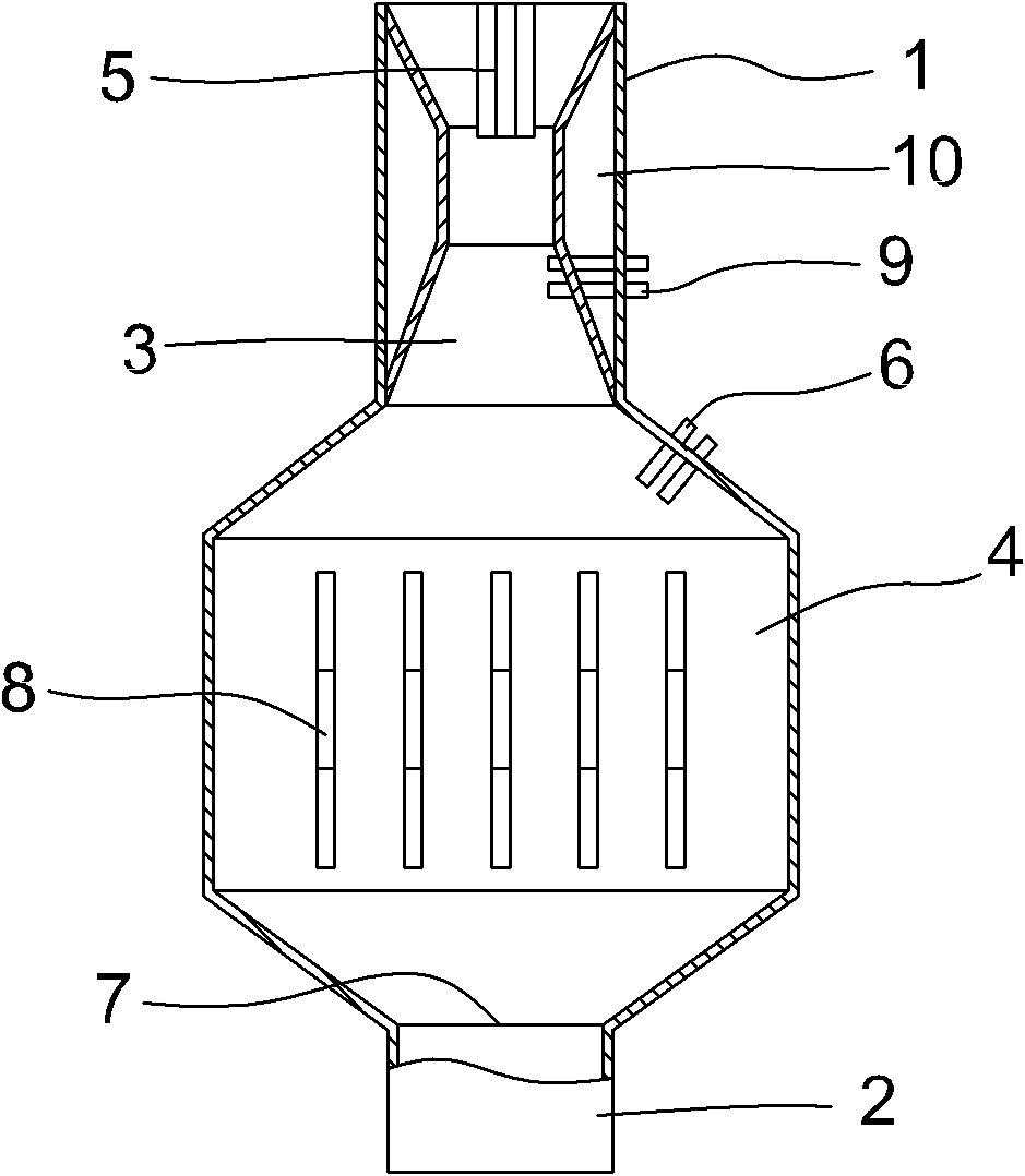
[0056] A reactor for the preparation of low-carbon olefins by thermal cracking reaction, the working state is vertical, and its structure is shown in the attached figure 1 , including the upper inlet port 1 and the lower outlet port 2. Among them, the space inside the inlet end 1, which accounts for 1 / 4 of the entire reactor length, is the combustion zone 3, and the remaining space is the reaction zone 4. The inner wall of the entire combustion zone 3 has a Venturi-type variable-diameter structure. A fuel and oxygen nozzle 5 is provided at the center of the inlet end, a temperature-regulating steam nozzle 9 is provided in the middle of the combustion zone 3, and three raw material nozzles 6 are provided at the diameter expansion of the combustion zone 3 entering the reaction zone 4; End 2 is provided with a product outlet 7 . In addition, there is a flow control system and a raw material distributor at the raw material nozzle 6, a flow control system at the fuel and oxygen n...

Embodiment 2

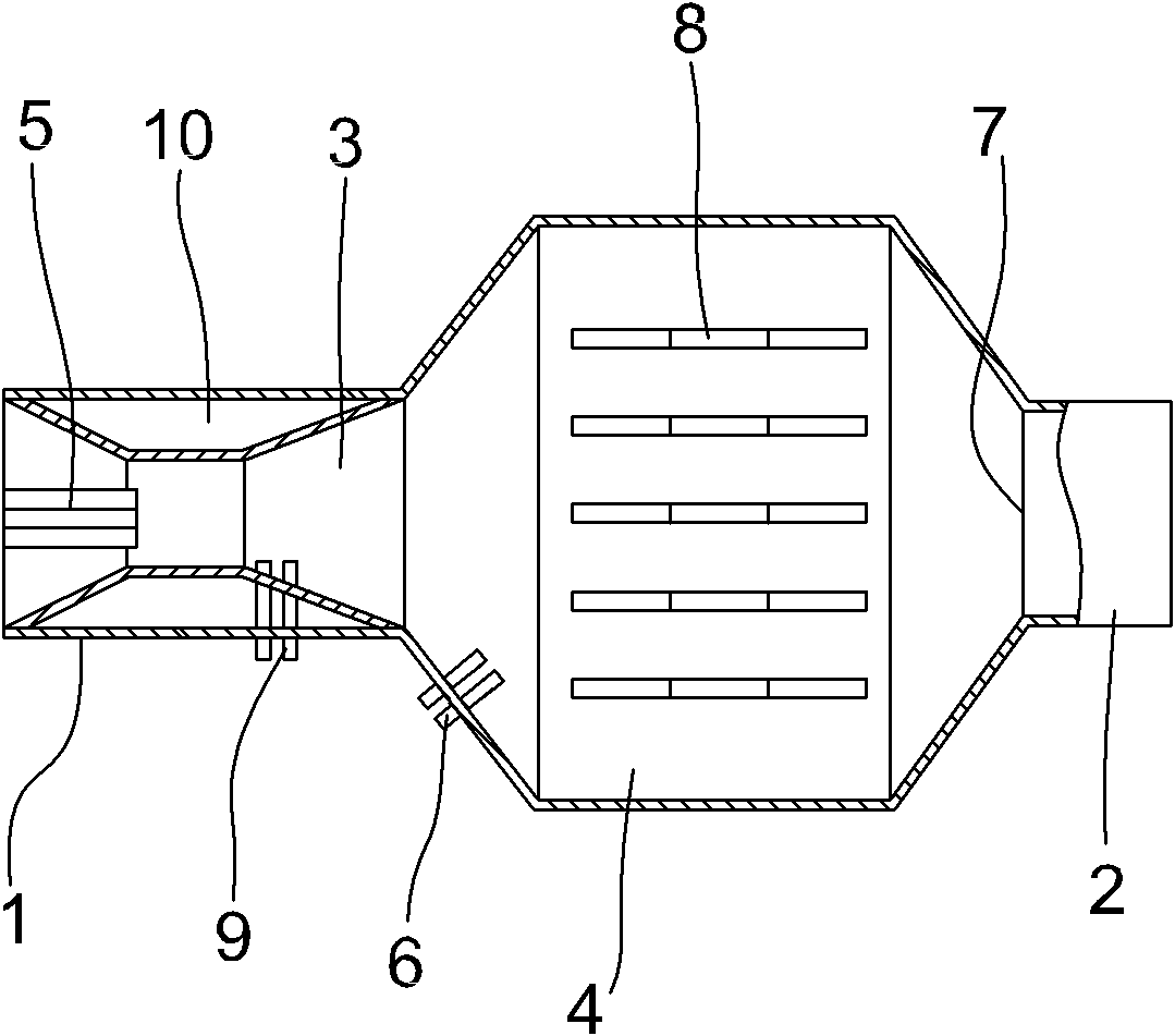
[0058] A reactor for the preparation of low-carbon olefins by thermal cracking reaction, the working state is horizontal, and its structure is shown in the attached figure 2 , with inlet port 1 on the left and outlet port 2 on the right. Among them, inside the inlet end 1, the space accounting for 1 / 4 of the entire reactor length is the combustion zone 3, and the remaining space is the reaction zone 4. The inner wall of the entire combustion zone 3 has a Venturi-type variable diameter structure, and the outer wall of the combustion zone is equipped with a cooling system. Jacket 10. Three fuel and oxygen nozzles 5 are arranged inwardly at the center of the inlet end, a temperature-regulating steam nozzle 9 is arranged in the middle of the combustion zone 3, and three raw material nozzles 6 are arranged at the expanding diameter of the combustion zone 3 entering the reaction zone 4; End 2 is provided with a product outlet 7 . In addition, there is a flow control system and a ...

Embodiment 3

[0060] A reactor for cracking reaction to prepare light olefins, the working state is vertical, its structure is shown in the attached figure 1 , including the inlet port 1 at the bottom and the outlet port 2 at the top. Wherein, inside the inlet port 1, the space accounting for 1 / 4 of the length of the entire reactor is the combustion zone 3, and the rest of the space is the reaction zone 4. The internal diameter of the combustion zone 3 is smaller than the internal diameter of the reaction zone 4. There are 2 fuel and oxygen nozzles 5; an inward raw material nozzle 6 is provided at the expanding diameter of the combustion zone 3 entering the reaction zone 4; a product outlet 7 is provided at the outlet end 2; 5 restrictor plates 8 distributed axially in parallel. In addition, there is a flow control system and a raw material distributor at the raw material nozzle 6, a flow control system at the fuel and oxygen nozzle 5, and a probe type flame combustion detection system in...


PUM


Abstract

The invention provides a reactor for preparing low-carbon olefins by cracking reactions, which has an entrance end (1) and an exit end (2), wherein the two ends are formed at opposite positions on the reactor; one fourth of the space from the entrance end (1) in the reactor is a combustion zone (3) and the rest space is a reaction area (4); the entrance end (1) is provided with a fuel and oxygen nozzle (5) communicated with the combustion zone (3), and the end ports except the nozzle are sealed; a reactor side wall between the combustion zone (3) and the reaction area (4) is provided with a raw material nozzle (6) and the exit end (2) has a product outlet (7); and the fuel and oxygen nozzle (5) and the raw material nozzle (6) are one or more than two nozzle structures. The invention also provides a method for preparing the low-carbon olefins by using the reactor.

Description

technical field [0001] The invention relates to a petrochemical process, and further relates to an equipment and method for preparing low-carbon olefins by cracking reaction. Background technique [0002] At present, the production technology of ethylene and propylene at home and abroad adopts the tubular steam cracking technology, that is, the cracking raw material is thermally cracked in the tube furnace tube with steam as a diluent under the conditions of high temperature, short residence time and low hydrocarbon partial pressure. , to produce ethylene, propylene, and by-products such as carbon four olefins, carbon five, and pyrolysis gasoline. This technology has a history of several decades, and representative patented technologies include LUMMUS, S.W, KBR in the United States and LIND in Germany. The typical olefin production process mainly includes cracking, quenching, compression, and separation. The representative patented technology is the cracking unit. Cracking ...

Claims


Application Information

Patent Timeline
IPC IPC(8): B01J19/26C07C4/04C10G9/00
CPCC10G2400/20B01J19/0013B01J2219/00382B01J2219/00164B01J2219/00157B01J19/26B01J19/24B01J4/002B01J19/006C10G9/00B01J2219/00085B01J12/005B01J2219/00083
Inventor 王仲华
Owner 王仲华
Learn More