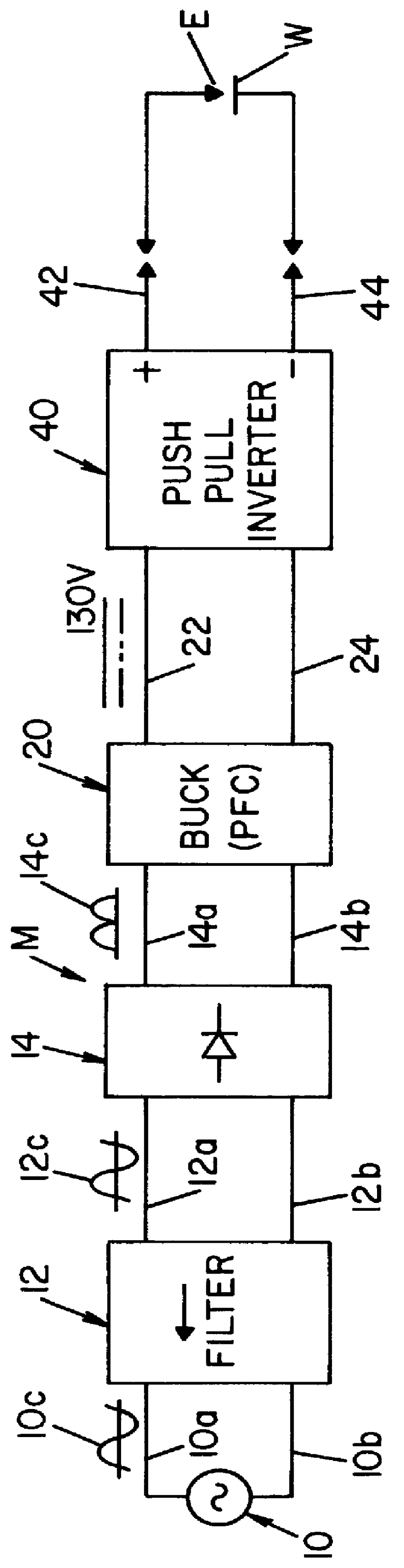
In accordance with the present invention, there is provided a single phase power supply module for electric arc welders and plasma arc cutters, which module comprises a single phase input stage, positive and negative output terminals, a
full wave rectifier connected to the input stage for rectifying the single phase voltage at the input stage and a
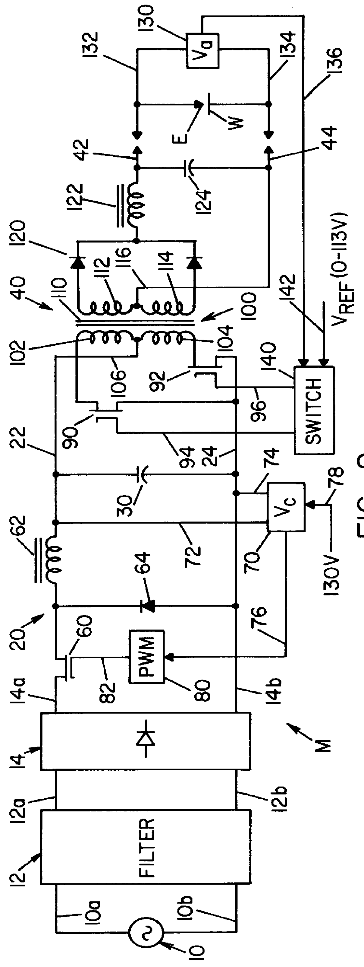
buck converter type power factor correcting circuit for controlling the current flow from the single phase input stage to the rectifier. In accordance with the invention, the buck converter has an output
capacitor regulated to an intermediate voltage in the range of 100-150 volts. Preferably, the output regulated voltage of the power factor correcting circuit is approximately 130 volts DC. Thus, the module has a low THD and a high power factor for the single phase input. In accordance with the invention, a high speed
DC to DC converter having an internal
transformer coupling applies the voltage of the
capacitor from the buck converter across the output terminals of the module and the applied voltage is regulated to an output voltage in a range of 0 to 113 volts. The output voltage of the single phase module is preferably between about 20-100 volts. This novel module has a
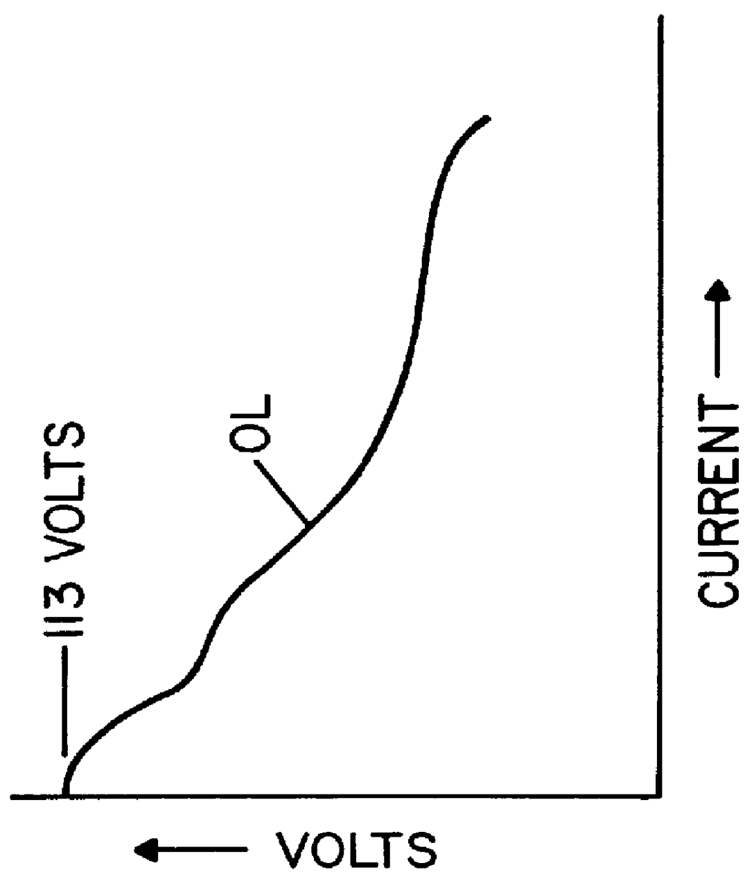
load line in the broadest aspect with an
open circuit voltage of 113 volts and, in a practical implementation, with an
open circuit voltage of 90 volts. An intermediate voltage of about 130 volts on the output capacitor of the power factor correcting circuit provides a maximum non-conduction angle of 60.degree. , which angle appears at the
low voltage portion of the incoming voltage. Thus,
distortion takes place at a
low energy level. This maximum non-conduction of the incoming current occurs when the input voltage is approximately 200 VAC. At 570 VAC, the non-conduction portion is only approximately 10.degree. and occurs at the
zero crossing of the input voltage. Consequently, extremely low
harmonics are created and little energy is consumed during non-conduction portions of the input current. The power factor is high and the
harmonic distortion is low when using a module constructed in accordance with the present invention. The module accepts input voltages in the range of 200-600 VAC with a smooth output voltage below 113 volts.
By employing the buck converter as a power factor correcting circuit and a
push pull converter to create the output voltage and current, the intermediate voltage of approximately 130 volts is lowered by the DC to
DC converter to create the
welding voltage. Thus, the stability, range and applicability of the universal module are increased. Since the module has an output voltage regulated by a pulse width modulator between 0-113 volts, the module itself is not used for plasma arc cutting. The module is used as a single phase electric arc welder having relatively low energy output. However, the basic use and
advantage of the universal module is combination of the module to create a
large range of welders and a
large range of cutters. In accordance with an aspect of the invention, the novel module includes an input
transformer for reducing the voltage of the single phase input source. By combining a buck converter to create the intermediate voltage of about 130 volts and an output converter with
galvanic isolation, the welder and cutter manufacturer need only a single power supply to offer a large number of individual units with different ratings.
The use of a module constructed in accordance with the present invention allows production of welders or cutters with the desired rating. Consequently, the manufacturer inventories a single module and merely combines such modules into the desired architecture to produce a complete line of welders and cutters. The use of this concept to develop a total line of the product is novel and will substantially reduce the inventory,
engineering cost, development activity, service efforts, related personnel and cost factors involving sale of a total line of welders and / or plasma arc cutters.
The primary object of the present invention is the provision of a single phase universal module that can be combined to produce a wide range of electric arc welders and / or plasma arc cutters to thereby create a range of welders and cutters without the need for different power supplies dedicated to each welder or cutter.
Another object of the present invention is the provision of a universal single phase module, as defined above, which module utilizes a buck converter with an output voltage in the range of 100-150 volts to minimize the THD and maximize the power factor of the module.
Still a further object of the present invention is the provision of a universal single phase module, as defined above, which module is economical to produce and can be used in a wide range of welders and cutters and requires a minimum inventory of power supplies for constructing a full line of electric arc welders and plasma arc cutters.

