Method for removing carbon dioxide from combustion exhaust gas

a technology of combustion exhaust gas and carbon dioxide, which is applied in the direction of hydrogen sulfides, sulfur compounds, separation processes, etc., can solve the problems of high absorption rate, and achieve the effect of improving the absorption rate of absorbents and high absorption ra

Inactive Publication Date: 2000-03-14
THE KANSAI ELECTRIC POWER CO +1
View PDF35 Cites 97 Cited by
  • Summary
  • Abstract
  • Description
  • Claims
  • Application Information

AI Technical Summary

Benefits of technology

As described above, a method for efficiently removing CO.sub.2 from a combustion exhaust gas has been heretofore desired. In particular, in the case that the combustion exhaust gas is treated with an aqueous solution containing a CO.sub.2 absorbent at a certain concentration, it is an urgent serious problem to select an absorbent which is capable of absorbing a large amount of CO.sub.2 per unit mole of the absorbent and absorbing a large

Problems solved by technology

In particular, in the case that the combustion exhaust gas is treated with an aqueous solution containing a CO.sub.2 absorbent at a certain concentration, it is an urgent serious problem to select an absorben

Method used


Image

  • Method for removing carbon dioxide from combustion exhaust gas
  • Method for removing carbon dioxide from combustion exhaust gas
  • Method for removing carbon dioxide from combustion exhaust gas

Examples


examples 6 to 8

Comparative Examples 2 to 4

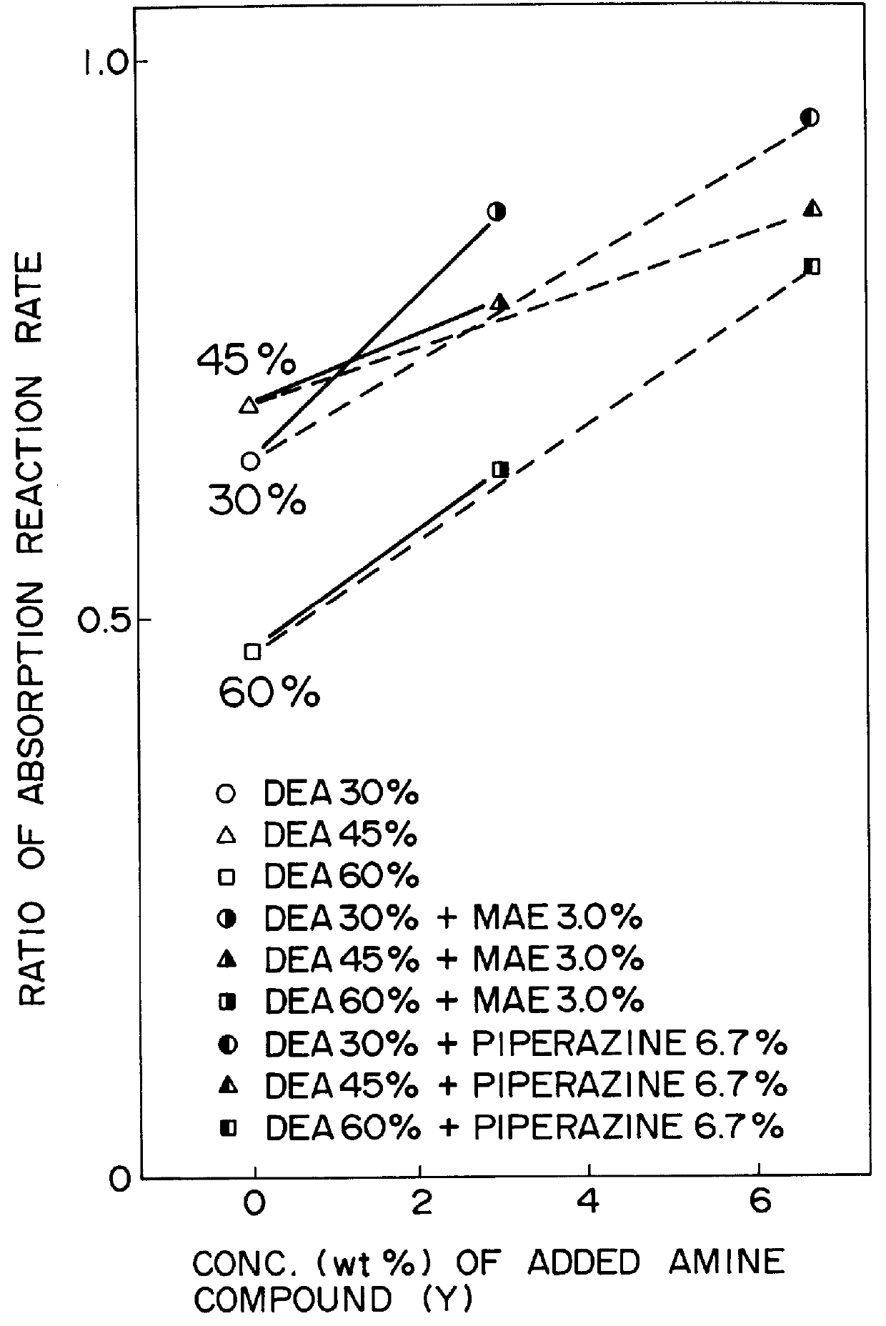
50 ml of an absorbing solution, i.e., an aqueous solution prepared by mixing an amine compound (X) selected from 2-amino-2-methyl-1-propanol (AMP), diethanolamine (DEA) and monoethanolamine (MEA) with an amine compound (Y) selected from 2-(methylamino)-ethanol (MAE) and piperazine in each ratio shown in Table 2 was placed in a glass reaction vessel (flask) disposed in a thermostatic chamber, and a mixed gas (a test gas) was fed to the flask with stirring at 40.degree. C. at a flow rate of 1 liter / minute under atmospheric pressure. The test gas used herein was a model combustion exhaust gas (which corresponds to an LNG-fired exhaust gas) at 40.degree. C. having a composition of 10 mole % of CO.sub.2, 3 mole % of O.sub.2 and 87 mole % of N.sub.2.

The test gas was continuously allowed to stream, and when the CO.sub.2 concentration of the fed gas was equal to that of the discharged gas, CO.sub.2 contained in the absorbing solution was measured by the use of a C...

example 9

Comparative Example 5

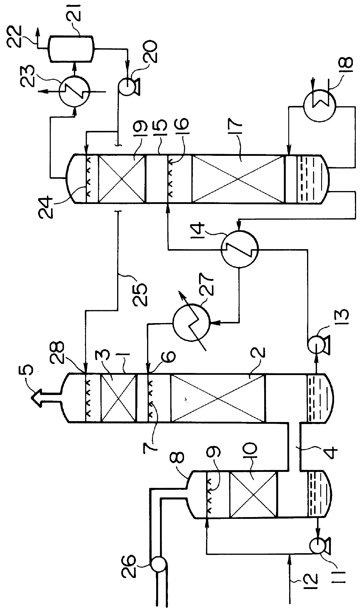
In order to inspect an effect of a reaction accelerator, a test was made by the use of a wet wall type absorbing tower having a diameter of 15 mm and a length of 7.5 mm which was the model of an absorbing tower used in an actual process. In this test, a 30% by weight DEAE solution was used as an absorbing solution, an actual boiler combustion exhaust gas (CO.sub.2 =9 mole %, O.sub.2 =2 mole %, water vapor =saturation state, N.sub.2 =mole % of balance) was used as a combustion exhaust gas, an L / G was 2.0 liters / m.sup.3 N, a liquid temperature and a gas temperature were both maintained at 40.degree. C., and a gas flow rate was 3.1 m / sec. The results are set forth in FIG. 5. In this FIG. 5, an ordinate axis was an absorption ratio of CO.sub.2 absorbed from the fed combustion exhaust gas, and an abscissa axis was a concentration of piperazine added to the absorbing solution. The absorption reaction acceleration effect of piperazine to DEAE was apparent from FIG. 5.

A...


PUM


Abstract

There are disclosed a method for removing CO2 from a combustion exhaust gas which comprises the step of bringing the combustion exhaust gas under atmospheric pressure into contact with an aqueous solution of a hindered amine selected from the group consisting of 2-amino-2-methyl-1-propanol, 2-methylaminoethanol, 2-ethylaminoethanol and 2-piperidineethanol; and another method for removing carbon dioxide from a combustion exhaust gas which comprises the step of bringing the combustion exhaust gas under atmospheric pressure into contact with a mixed aqueous solution of 100 parts by weight of an amine compound (X) selected from the group consisting of 2-amino-2-methyl-1,3-propanediol, 2-amino-2-methyl-1-propanol, 2-amino-2-ethyl-1,3-propanediol, t-butyldiethanolamine and 2-amino-2-hydroxymethyl-1,3-propanediol; and 1-25 parts by weight of an amine compound (Y) selected from the group consisting of piperazine, piperidine, morpholine, glycine, 2-methylaminoethanol, 2-piperidineethanol and 2-ethylaminoethanol.

Description

FIELD OF THE INVENTION AND RELATED ART STATEMENTThe present invention relates to a method for removing CO.sub.2 (carbon dioxide) from a combustion exhaust gas. More specifically, it relates to a method for removing CO.sub.2 from a combustion exhaust gas under atmospheric pressure by the use of a specific mixed aqueous solution containing an amine.In recent years, a greenhouse effect by CO.sub.2 is indicated as one cause of the warming phenomenon of the earth, and its prompt resolution is globally required in order to protect earth circumstances. The generation sources of CO.sub.2 extend in active fields of all humans in which fossil fuels are burned, and there is a tendency that the discharge regulation of CO.sub.2 will be further tightened in the future. Thus, for power generation facilities such as thermoelectric power plants in which a large amount of the fossil fuel is used, there are energetically researched a method for removing and recovering CO.sub.2 from a combustion exhaus...

Claims


Application Information

Patent Timeline
IPC IPC(8): B01D53/14
CPCB01D53/1475B01D53/1493Y02C10/04Y02C10/06Y02A50/20Y02C20/40B01D53/92
Inventor YOSHIDA, KUNIHIKOMIMURA, TOMIOSHIMOJO, SHIGERUKARASAKI, MUTSUNORIIIJIMA, MASAKISETO, TOURUMITSUOKA, SHIGEAKI
Owner THE KANSAI ELECTRIC POWER CO
Why Eureka
Try Eureka