Liquid crystalline polymer film, laminate sheet for optical element using same, and optical element using the laminate

a technology of liquid crystal polymer and laminate sheet, which is applied in the direction of film/foil adhesive, other domestic articles, transportation and packaging, etc., can solve the problems of affecting the production efficiency of the film, the inability to produce a long laminate sheet directly, and the inability to produce a long laminate sheet. achieve the effect of improving productivity and economy, improving economy and yield

Inactive Publication Date: 2000-04-18
NIPPON PETROCHEMICAL CO LTD
View PDF11 Cites 53 Cited by
  • Summary
  • Abstract
  • Description
  • Claims
  • Application Information

AI Technical Summary

Benefits of technology

In a certain process it is also possible to laminate an obliquely oriented long film after continuous production as it is to the polarizing sheet without once winding it up in a roll form. Also in this case, however, at least the polarizing film should be delivered from a roll because in many cases it is supplied in a roll form. By so doing, it becomes possible to effect a continuous operation. (Not only in the case where both liquid crystalline film and polarizing film are rolled, but also in such a case as just mentioned above), the film supply mode is sometimes called "roll to roll" herein.
1) Since a long, liquid crystalline polymer film can be produced continuously, both productivity and economy.-are improved.
2) Since the angle of orientation of the liquid crystalline polymer can be controlled as desired, the polymer film pieces can be cut out without waste at the time of assembling an optical element, whereby both economy and yield are improved.
Furthe

Problems solved by technology

For example, in the case of a long film, the orienting direction of the film is inevitably limited corresponding to the stretched direction of the film.
That is, as long as the aforesaid film for opticl element and the aforesaid polarizing sheet each utilized a uniaxially stretched film, the orienting direction or transmission axis direction thereof is inevitably limited by the stretched direction of the film.
Accordingly, as long as a uniaxially stretched film with the orientation direction or transmission axis direction fixed in TD or MD is utilized, it has actually been difficult heretofore to produce a long laminate of films directly.
Although such conventional cutting-out and laminating operations are performed manually and carefully, the occurrence of rejected products has heretofore been unavoidable because it is necessary to make an angular adjustment of directions accurately.
It has also been impossible inevitably to expect any improvement of productivity.
Besides, since it is necessary that a square piece be cut out obliquely from

Method used


Image

  • Liquid crystalline polymer film, laminate sheet for optical element using same, and optical element using the laminate

Examples


preparation example 1

(Preparation Example 1 of Liquid Crystalline Polymer Solution)

There was prepared a 20 wt % solution in dimethylformamide of a polymer mixtue (inherent viscosity of a base polymer: 0.21, Tg=60.degree. C., inherent viscosity of an optically active polymer: 0.18) represented by the following formula (1-I): ##STR45## (Preparation Example 2 of Liquid Crystalline Polymer Solution)

There was prepared a 15 wt % solution in phenol / tetrachloroethane (60 / 40 weight ratio) of a single polymer (inherent viscosity of a base polymer: 0.18 Tg=95.degree. C.) represented by the following formular (1-II): ##STR46##

example 1

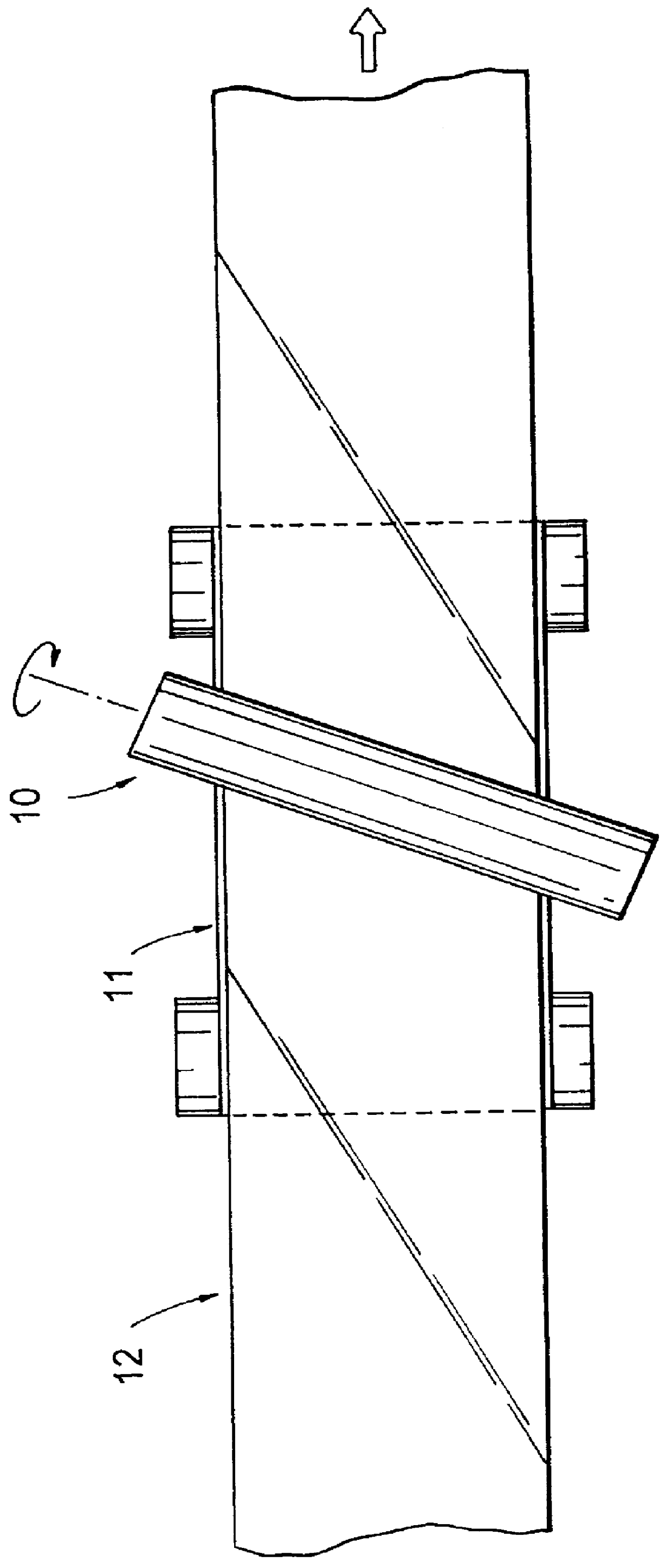
The apparatus shown in FIG. 1 was used. While a PEEK film having a width of 50 cm and a thickness of 100 m, serving as an orienting substrate, was moved at a rate of 20 m / min, a rubbing roll having a diameter of 150 mm and with nylon cloth wound thereon was set at 45.degree. relative to the MD direction of the PEEK film and was rotated at 1,500 rpm and at a pushing-in amount of 500 .mu.m of fiber tips of the nylon cloth. In this way rubbing was performed continuously and the rubbed film was taken up onto a roll.

The rubbing angle, which was 45.degree., is here assumed to be a clockwise angle from the MD direction when the rubbed surface is seen from above.

The liquid crystalline polymer solution prepared in Preparation Example 1 was applied onto the rubbed, long film by means of a roll coater, then dried and subsequently heated at 200.degree. C. for 40 minutes to fix the orientation of the liquid crystalline polymer.

Twist angle and .DELTA.n.multidot.d of the compensating layer thus ob...

example 2

The orientation-fixed liquid crystalline polymer prepared in Example 1 was transferred onto a polyethylene terephthalate (PET) film using a pressure-sensitive adhesive in accordance with a conventional method to afford a laminate sheet of liquid crystalline polymer layer / PET.

Then, an ultraviolet curing type acrylic resin layer was formed as a protective layer on the surface of the liquid crystalline polymer layer and thereafter a commercially available, long polarizing sheet was laminated to the protective layer side using a pressure-sensitive adhesive with roll to roll. The commercial polarizing sheet used was the same as that used in Example 1.

As a result, there was obtained a long laminate sheet comprising polarizing sheet / pressure-sensitive adhesive layer / photocured acrylic resin layer / liquid crystalline polymer layer / pressure-sensitive adhesive layer / PET FILM.

In this laminate sheet, the polymer molecules in the liquid crystalline polymer layer on the polarizing sheet side were ...


PUM

PropertyMeasurementUnit
Lengthaaaaaaaaaa
Lengthaaaaaaaaaa
Lengthaaaaaaaaaa

Abstract

To provide a film for optical element made of liquid crystal polymer whose productivity and economical efficiency are improved; a laminated sheet formed by bonding this film to a polarizing plate; and an optical element which can be optically inspected, and used under an environment of high temperature and high moisutre, and whose surface hardness is so high that the surface is not easily damaged. A long laminated sheet for optical element comprising a liquid crystal polymer layer, and a polarizing film layer; and a long laminated sheet for optical element comprising at least a liquid crystal polymer film layer oriented in the direction oblique to the MD direction at a given angle, and a polarizing film layer. An optical element having a laminated structure formed by laminating a layer of a cured acrylic resin having optical isotropy, an orientated liquid crystal polymer layer, a layer of pressure-sensitive adhesive, and a translucent base layer in that order, and a long laminated sheet for optical element having a laminated structure formed by laminating a layer of a cured acrylic resin having optical isotropy; an oriented liquid crystal polymer layer; a layer of pressure-sensitive adhesive; and a translucent base layer in that order, and a containing liquid crystal polymers orientated in the MD direction at an arbitrary angle.

Description

The present invention relates to a long, continuous, liquid crystalline polymer film oriented at a desired angle which film is to be used for an optical element such as a color compensator for a liquid crystal display, a viewing angle compensator for a liquid crystal display, a retardation plate, a half-wave plate, a quarter-wave plate or an optical rotator.The present invention also relates to a long, continuous, film-like laminate sheet including a liquid crystalline polymer layer which sheet is to be used for an optical element such as a color compensator for a liquid crystal display, a viewing angle compensator for a liquid crystal display, a retardation plate, a half-wave plate, a quarter-wave plate or a rotator.Particularly, the invention relates to a long, continuous, laminate sheet for an optical element which sheet is a laminate of a liquid crystalline polymer layer and a polarizing film layer, the liquid crystalline polymer layer being oriented in a specific direction.The ...

Claims


Application Information

Patent Timeline
IPC IPC(8): C09K19/38C09K19/40
CPCC09K19/38C09K19/408Y10T428/1041C09K2323/031
Inventor TSUJIMOTO, YOSHIOISHIKAWA, HIROYASUMUKAI, JUNYAMANASHI, TERUAKIICHIZUKA, TOSHIHIROHOSAKI, KENJI
Owner NIPPON PETROCHEMICAL CO LTD
Why Eureka
Try Eureka