Heater well method and apparatus

a well and well technology, applied in the direction of fluid removal, insulation, borehole/well accessories, etc., can solve the problems of unfavorable economics of oil recovery and soil remediation, vaporizing contaminants and driving them to production wells, and even destroying contaminants in situ,

Inactive Publication Date: 2000-06-27
SHELL OIL CO
View PDF7 Cites 397 Cited by
  • Summary
  • Abstract
  • Description
  • Claims
  • Application Information

AI Technical Summary

Problems solved by technology

In the case of soil remediation, uniform heating of the soil by thermal conduction can vaporize contaminants and drive them to production wells, or even destroy the contaminants in situ.
However, electric heating is generally expensive due to a higher per-BTU cost of electricity as opposed to hydrocarbon fuels.
This relatively high energy cost can unfavorably affect the economics of oil recovery and soil remediation.
However, it is difficult to uniformly heat thick earth formations, especially when those formations are below overburdens of hundreds of feet.
Existing burner technology would result in large temperature variations between the top and bottom of the heated interval and non-uniform heating of the earth formation.
The radiant heat source within the wellbores requires that expensive materials be used for major portions of the wellbore tubulars.
With downhole gas-fired burners, the well casing adjacent to the burner becomes significantly hotter than the average well temperature, result...

Method used


Image

  • Heater well method and apparatus
  • Heater well method and apparatus
  • Heater well method and apparatus

Examples


Embodiment Construction

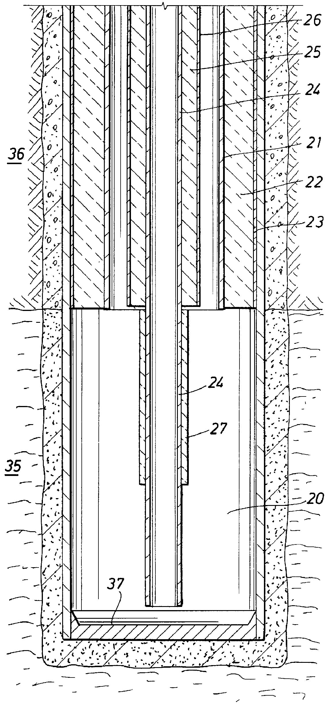
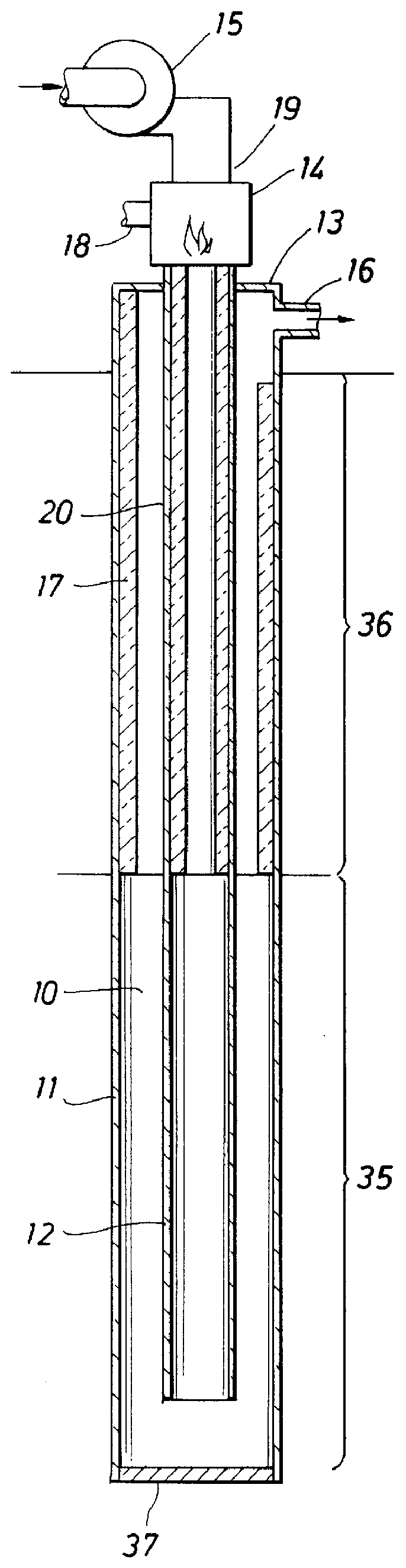
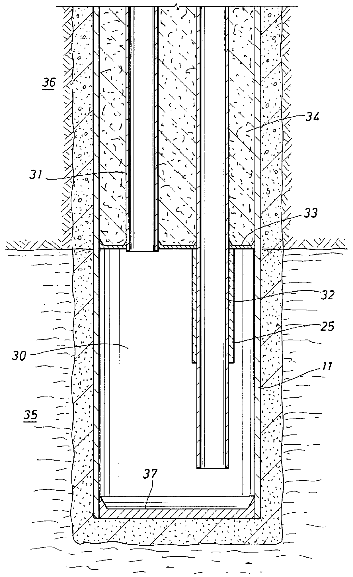
Referring now to FIG. 1, there is shown a heater well 10, including a casing tubular 11 which is sealed at the bottom with a cement or metal plug 37. The heater well traverses an overburden 36 and a target formation 35. A combustion gas flowpath tubular 12 inside the casing extends to near the bottom of the target formation. The combustion gas flowpath is open at the bottom, and a volume within the combustion gas flowpath tubular is therefore in communication with the annular volume surrounding the combustion gas flowpath tubular. A wellhead 13 at the surface seals the casing. A burner 14 is attached to the wellhead. Inlet air from air source 15 (blower shown) supplies inlet air to the burner through the wellhead. Combustion gases from the burner leave the overburden section 36 at a temperature of about 1800.degree. F. with little heat loss in the overburden because insulation 20 is provided between the tubular and the annular volume surrounding the tubular, inside of the casing 11....


PUM


Abstract

A method and apparatus is disclosed for heating of formations using fired heaters. The method includes the steps of: providing a wellbore within the formation to be heated, the wellbore comprising a casing within the formation to be heated, a tubular defining, in the inside of the tubular, a flowpath for hot gases from the surface to a point in the wellbore near the bottom of the formation to be heated, and a volume between the tubular and the casing providing a flowpath for hot gases from near the bottom of the formation to be heated to the top of the formation to be heated, wherein the flowpaths are in communication with each other near the bottom of the formation to be heated and the volume between the casing and the tubular at the top of the formation to be heated is in communication with a point above the surface, and insulation for a portion of the length of the wellbore within the formation to be heated between the flowpath for hot gases from the surface to the point in the wellbore near the bottom of the formation to be heated and the flowpath for hot gases from near the bottom of the formation to be heated to the surface; and supplying a flow of hot gases to the flowpath for hot gases from the surface to a point in the wellbore near the bottom of the formation to be heated.

Description

The present invention relates to a method and apparatus to heat subterranean formations.BACKGROUND TO THE INVENTIONNumerous applications exist in oil production and soil remediation where it is desired to uniformly heat thick sections of the earth using thermal conduction. In the case of oil production, there exist enormous worldwide deposits of oil shale, tar sands, lipid coals, and oil-bearing diatomite where uniform heating of the hydrocarbonaceous deposit by thermal conduction can be used to recover hydrocarbons as liquids or vapor. The thickness of the deposits can be hundreds of feet thick, and lie beneath overburden hundreds of feet thick. In the case of soil remediation, uniform heating of the soil by thermal conduction can vaporize contaminants and drive them to production wells, or even destroy the contaminants in situ. Here, the contamination can extend from the soil surface down hundreds of feet.Electric heat can be used for uniform heating of thick earth formations by t...

Claims


Application Information

Patent Timeline
IPC IPC(8): E21B36/02E21B36/00
CPCE21B36/025
Inventor MIKUS, THOMASWELLINGTON, SCOTT LEEKARANIKAS, JOHN MICHAELVINEGAR, HAROLD J.
Owner SHELL OIL CO
Why Eureka
Try Eureka