High-frequency electrodeless fluorescent lamp

a fluorescent lamp and high-frequency technology, applied in the direction of discharge tube main electrodes, discharge tube luminescnet screens, lighting and heating apparatus, etc., can solve the problems of limited actual efficiency of the whole system, limited power loss of coil wires, and increased power losses of coil wires

Inactive Publication Date: 2000-06-27
MATSUSHITA ELECTRIC WORKS LTD
View PDF7 Cites 54 Cited by
  • Summary
  • Abstract
  • Description
  • Claims
  • Application Information

AI Technical Summary

Problems solved by technology

The actual efficiency of the whole system., that includes a lamp, a matching network, and an RF power driver, is limited by the efficiency of an RF power driver that is relatively low at a frequency of 13.56 MHz and hardly exceeds 83%.
However, the increase of the number of turns and the coil current leads also to the substantial increase of power losses in coil wire, P.sub.coil =I.sub.coil.sup.2 R.sub.coil.
These losses could be substantial in lamps where high voltage and, hence, high coil current and high magnetic field are needed for lamp starting.
High power losses-substantially reduce the lamp efficiency.
The increase of the coil voltage is also not desirable because it leads to the increase of the RF voltage in the plasma-wall sheath that in turn causes the growth of energy of ions bombarding the phosphor coated walls.
However, this current generates its own magnetic field of the opposite direction that results in the lower coil inductance.
A smaller Q factor thereby increases the coil current, I.sub.coil, and, hence, increases the power losses in the coil wire.
This approach works well at RF-powers up to 80 W, however, the lamp construction becomes complicated and more expensive.
However, this approach is not applicable for a lamp having a central tubulation.
Moreover, the introduction of the solid metal rod inside of the coil / ferrite assembly causes, inevitably, power losses associated with eddy current induced in the solid rod by the time-variable and radially nonuniform magnetic field generated by the coil / ferrite assembly.
With such a small cross section, it is impossible to remove a substantial amount of heat generated by 40-60 W plasma.
Second, it is impossible to place a solid rod at the cavity axis in the presence of the central tubulation and, therefore, the Antonis et al. patent is not applicable to electrodeless lamps having the tubulation located on the axis of the cavity but on the side of the cavity or on the top of the envelope.
This results in higher power loss and a substantial reduction of the combined coil / ferrite / shield inductance.
All these factors make it impractical to use a slotted metal cylinder / Faraday shield between the coil and the cavity walls at low frequencies of 50-300 KHz.
Many features of the electrodeless lamps described in the prior art are suitable for lamps operated at frequencies of 2.65-13.56 MHz, but are not suitable for lamps operated at low frequencies of 50-1000 KHz.

Method used


Image

  • High-frequency electrodeless fluorescent lamp
  • High-frequency electrodeless fluorescent lamp
  • High-frequency electrodeless fluorescent lamp

Examples


Embodiment Construction

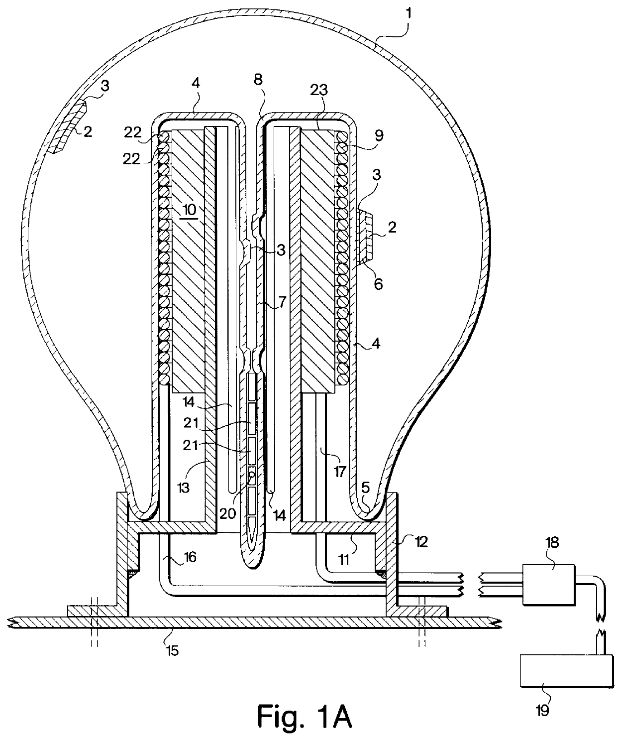
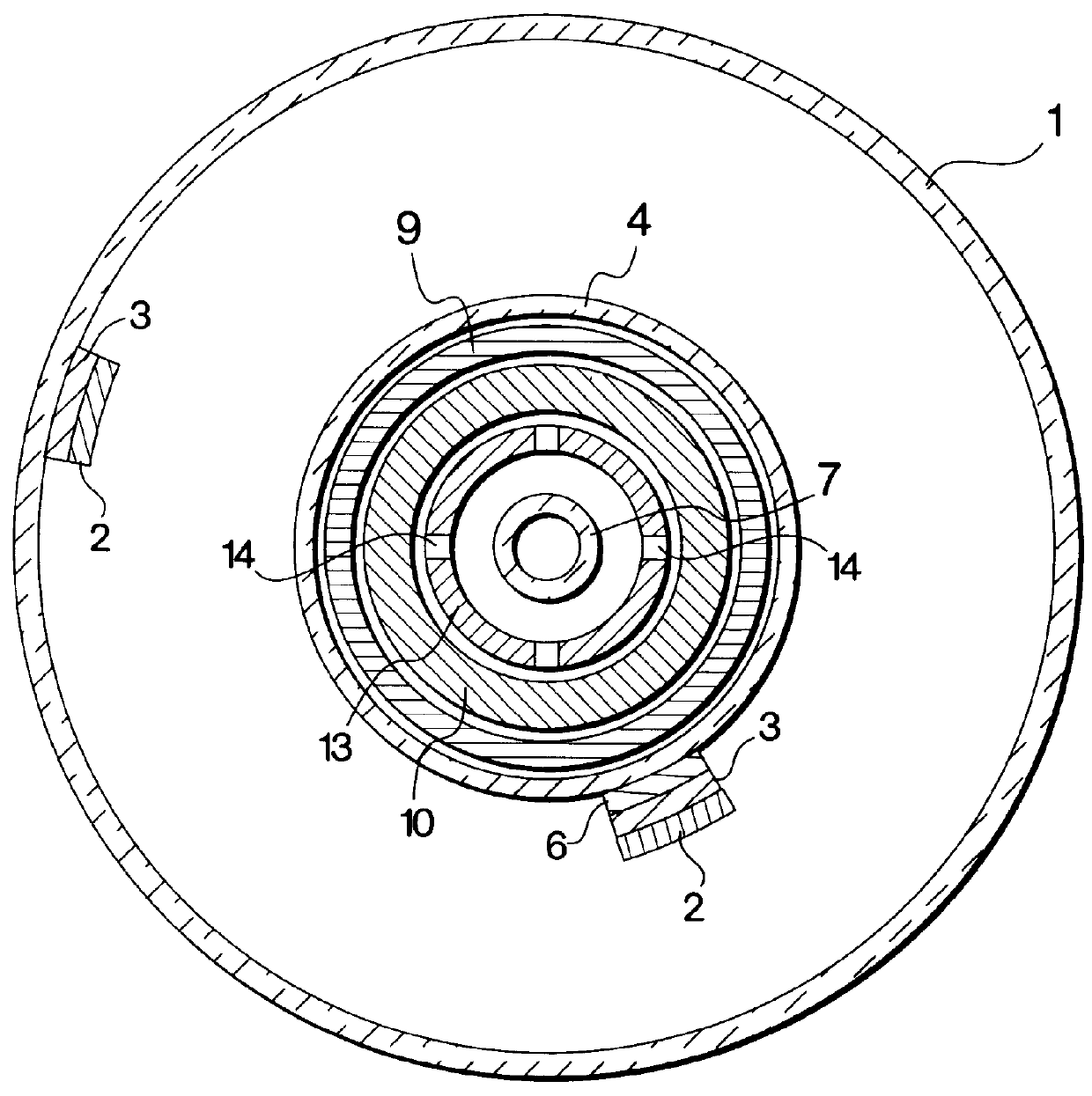
Referring to FIGS. 1a and 1b, a bulbous envelope 1 is shown with a coating 2 of a conventional phosphor. A protective coating 3 formed of silica or alumina, or the like, is disposed between the envelope 1 and the phosphor coating 2. The envelope 1 has a reentrant cavity 4 disposed in the bottom 5. The inner walls of the reentrant cavity 4 also have the phosphor coating 2 and the protective coating 3. A reflective coating 6 is disposed between the phosphor coating 2 and the protective coating 3. The protective coating 2 is also disposed on the inner walls of an exhaust tubulation 7. The tubulation 7 can be disposed on the envelope axis or off the envelope axis. In the preferred embodiment, the tubulation 7 is disposed on the envelope axis and connected to the envelope at the upper part 8 of the inner cavity 4. The envelope 1 contains a mixture of inert gas such as argon or krypton, or the like, and a vaporizable metal, such as mercury, sodium and / or cadmium.

An induction coil 9 is for...


PUM


Abstract

An electrodeless fluorescent lamp and fixture which operates at the frequency range of 50-1000 KHz and power from 20 to 200 W is disclosed. The lamp includes a bulbous envelope (1) filled with rare gas and metal vapor and a reentrant cavity (5). The inner walls of the envelope are coated with phosphor (2) and a protective coating (3). An induction coil (9), made from multiple strands of wire having very low resistance at frequencies below 1000 KHz, together with a ferrite core (10), having high permeability and low power losses, generates an inductively-coupled plasma in the envelope volume. The plasma generates visible and UV radiation that is converted into visible light by the phosphor coated on the envelope walls. A metallic cylinder (13), placed inside the ferrite core (10), removes the heat generated by the plasma from the coil and ferrite core and redirects the heat to the lamp base and thence to the lamp fixture. The power efficiency of the lamp operated at frequencies 200-300 KHz and its efficacy are the same as those in electrodeless RF lamps operated at frequencies of 2.65 MHz and at 13.56 MHz.

Description

BACKGROUND OF INVENTIONThis invention relates to electrodeless fluorescent lamps, and particularly to improvements in the efficiency of such lamps.DESCRIPTION OF THE PRIOR ARTDuring the last several years inductively-coupled electrodeless fluorescent lamps have been introduced for indoor and outdoor illumination. These lamps employ an inductively-coupled plasma for efficient generation of visible and UV light, and have lifetimes much longer than conventional fluorescent lamps that employ hot cathodes.In an electrodeless inductively-coupled lamp described in the prior art, U.S. Pat. No. 5,621,266 to Popov et al., the plasma was excited in an envelope filled with the mixture of rare gas (Kr, Ar, Xe) and metal vapor (mercury, sodium, and / or cadmium). The RF plasma was maintained by the azimuthal RF electric field, E.sub.ind, induced in the envelope volume by the magnetic field, B. This magnetic field is generated by the RF current in the induction coil that is inserted in the reentrant...

Claims


Application Information

Patent Timeline
Patent Type & Authority Patents(United States)
IPC IPC(8): H01J65/04F21S2/00
CPCH01J65/048
Inventor POPOV, OLEG A.NANDAM, PRADEEP K.SHAPIRO, EDWARD K.MAYA, JAKOB
Owner MATSUSHITA ELECTRIC WORKS LTD
Why Eureka
Try Eureka