

Method and apparatus for gas phase diffusion coating of workpieces made of heat resistant material
- Summary
- Abstract
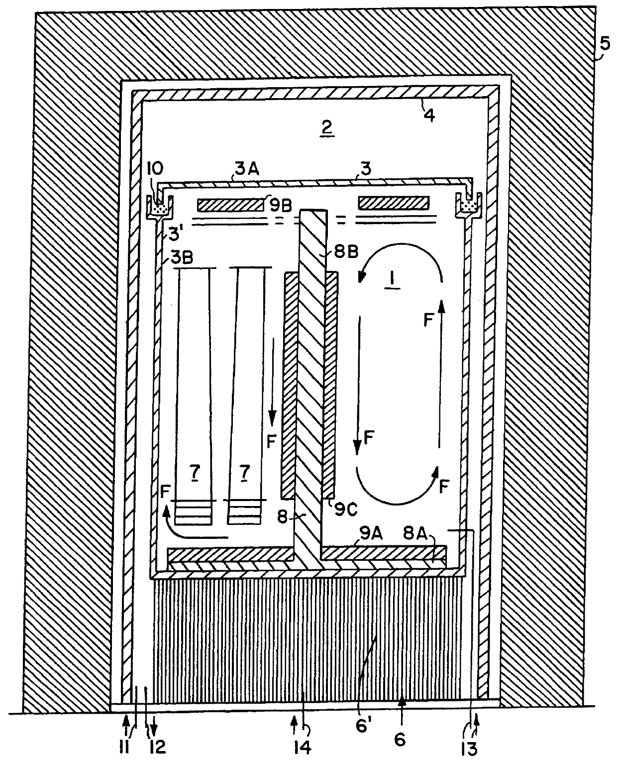
- Description
- Claims
- Application Information
AI Technical Summary
Benefits of technology
Problems solved by technology
Method used
Image

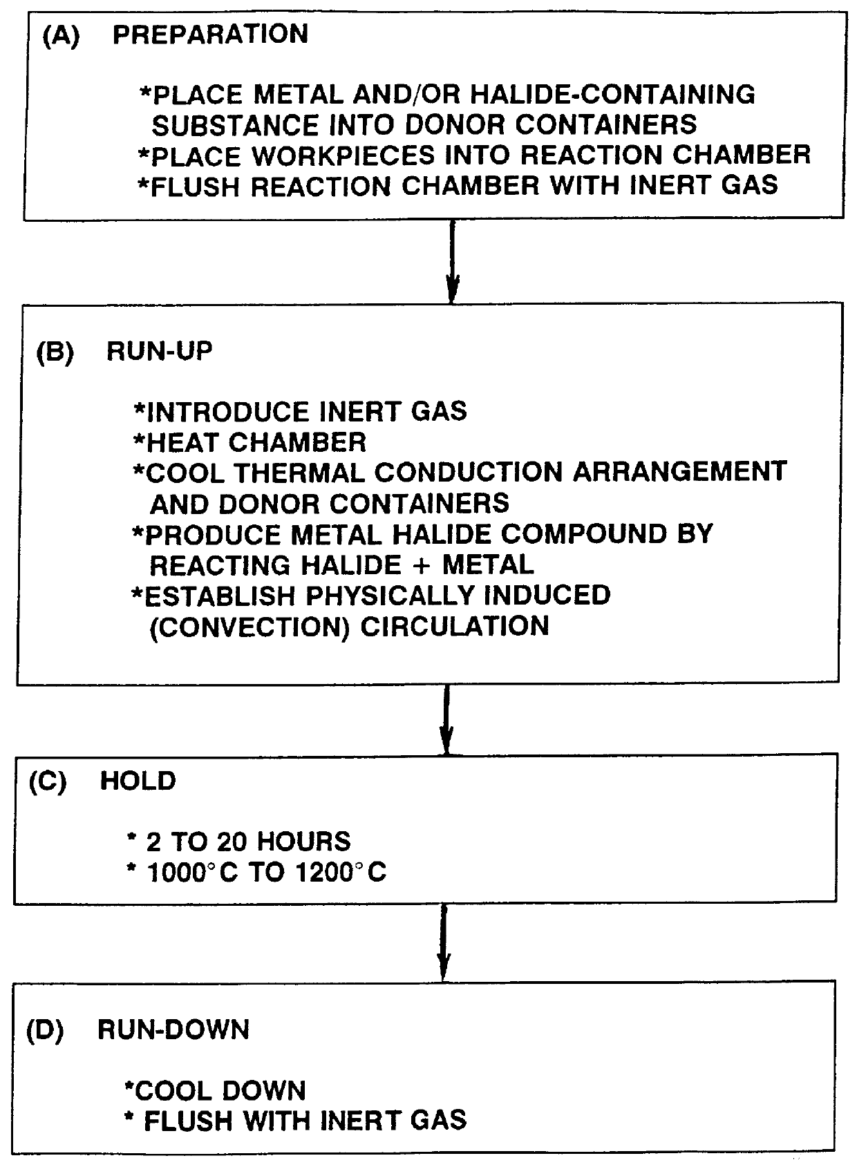
Examples
example 1
In this example, the workpieces 7 are turbine blades made of the alloy MAR-M-247, having a length of 710 mm. These turbine blades were subjected to the gas phase diffusion process according to the invention, to provide a chrome layer having a thickness of 70 .mu.m on the surfaces of the blades. Specifically, ten to twenty-four turbine blades are charged into the reaction chamber 1. 54 kg of Cr granules uniformly mixed with 540 g of ammonium chloride are supplied into the metal donor containers 9A, 9B and 9C. The reaction chamber 1 and the retort chamber 2 are flushed out for at least 30 minutes using argon at a flow rate of 2 m.sup.3 / h. Heating is carried out from room temperature to 1140.degree. C. over a time of 2.5 hours, whereby argon is introduced at a rate of 0.5 m.sup.3 / h until a temperature of 700.degree. C. is reached. Once the system is at high temperature, a temperature difference or gradient between the work pieces 7 and the metal donor containers 9A, 9B and 9C is in a...
example 2
In Example 2, the workpieces comprise turbine blades made of a nickel based alloy Rene 80, which are to be coated according to the method of the invention with an aluminum diffusion layer having a thickness of 80 .mu.m. Up to thirty-two of the turbine blades are arranged in one plane within the reaction vessel. 48 kg of AlCr granules having 50 wt. % Al are mixed with 320 g of AlF.sub.3 as a donor of the halogen, and this mixture is placed into the donor containers 9A, 9B and 9C. The reaction chamber 1 is heated, and during the heating up to 700.degree. C. the reaction chamber is flushed with 2 m.sup.3 / h of argon, and in the temperature range from 700.degree. C. to 1000.degree. C. the reaction chamber 1 is flushed with H.sub.2. The diffusion coating process is carried out at a high temperature of 1080.degree. C. for a holding time of 4.5 hours. A coating layer comprising 33 wt. % Al and having a layer thickness of 65 to 80 .mu.m was formed on the surfaces of the workpieces.
PUM
| Property | Measurement | Unit |
|---|---|---|
| Temperature | aaaaa | aaaaa |
| Temperature | aaaaa | aaaaa |
| Fraction | aaaaa | aaaaa |
Abstract
Description
Claims
Application Information