Abrasive liquid slurry for polishing and radiusing a microhole

a technology of abrasive liquid and micro-hole, which is applied in the direction of grinding devices, other chemical processes, manufacturing tools, etc., can solve the problems of large difficulty, thin wall projection, and substantial impede the fluid flow, and achieve low viscosity of slurry, low abrasiveness, and tight process control

Inactive Publication Date: 2000-10-17
EXTRUDE HONE CORP
View PDF14 Cites 22 Cited by
  • Summary
  • Abstract
  • Description
  • Claims
  • Application Information

AI Technical Summary

Benefits of technology

Such deviations are necessarily tolerated within broad limits and the attendant compromises in design freedom, performance and efficiency are accepted as unavoidable. For example, the delivery of fuel charges to internal combustion engines by pressurized fuel injection requires metering of flow through injector nozzles. The more precisely the flow can be regulated, the greater the fuel efficiency and economy of the engine operation.
With diesel fuel injector nozzles, it has been found desirable to radius the inlet side of the injector microholes in order to eliminate stress risers and pre-radius the upstream edge to minimize changes in emissions over the design life of the nozzle. Conventional abrasive flow machining can effectively produce radii on microholes, but fine control of the final injector flow rate has been impossible to achieve. The high, putty-like viscosity and highly elastic character of conventional abrasive flow media are too radically different from the characteristics of diesel fuel to permit either in-process gauging or adaptive control of this process. Furthermore, the very small quantity of abrasive flow media required to produce the desired radius limits process resolution.
In a preferred embodiment, the invention is directed to radiusing and sizing the microholes in diesel fuel injectors using a liquid abrasive slurry with particular Theological properties. the abrading action at the inlet edge of the microhole results from the acceleration of slurry velocity as it enters the microhole. The radius produced and the finish imparted to the microhole is similar to that of abrasive flow machining. However, the relatively low slurry viscosity and its low abrasiveness at low velocity enables the use of a flow meter in the slurry flow path which can directly and accurately monitor slurry flow rate and slurry mass flow in real time. Therefore, tight process control is attained as compared with conventional abrasive flow machining. In the preferred embodiment of the invention, the slurry flow is correlated to diesel fuel flow rates. This allows for individual slurry processing of nozzles to their specified flow rates.

Problems solved by technology

However, due to manufacturing artifacts, it is of great difficulty.
In the extreme case, a very slight crack in a core can lead to a thin wall projecting into an internal passage.
All these artifacts will substantially impede fluid flow.
Commonly employed machining methods, such as conventional drilling, electrical discharge machining and even less usual techniques as laser, electron beam and electrochemical techniques are not sufficiently precise to avoid the generation of substantial variations in flow resistance.
Probably, the most precise of these, electrical discharge machining, will not produce perfectly uniform flow resistance because non-uniform EDM conditions are inevitable and may produce variations in size, shape, surface finish and hole edge conditions.
Such deviations are necessarily tolerated within broad limits and the attendant compromises in design freedom, performance and efficiency are accepted as unavoidable.
The inventory requirements for the matching of components is quite substantial and therefore very costly.
In addition, a substantial number of components must be rejected as out of allowable deviations and must be reworked at considerable expense or discarded.
Conventional abrasive flow machining can effectively produce radii on microholes, but fine control of the final injector flow rate has been impossible to achieve.
The high, putty-like viscosity and highly elastic character of conventional abrasive flow media are too radically different from the characteristics of diesel fuel to permit either in-process gauging or adaptive control of this process.
Furthermore, the very small quantity of abrasive flow media required to produce the desired radius limits process resolution.
Briefly, in abrasive flow machining (AFM) of microholes the flow rate of the material does not correlate well to the flow rate of the target liquid.

Method used


Image

  • Abrasive liquid slurry for polishing and radiusing a microhole
  • Abrasive liquid slurry for polishing and radiusing a microhole
  • Abrasive liquid slurry for polishing and radiusing a microhole

Examples


Embodiment Construction

)

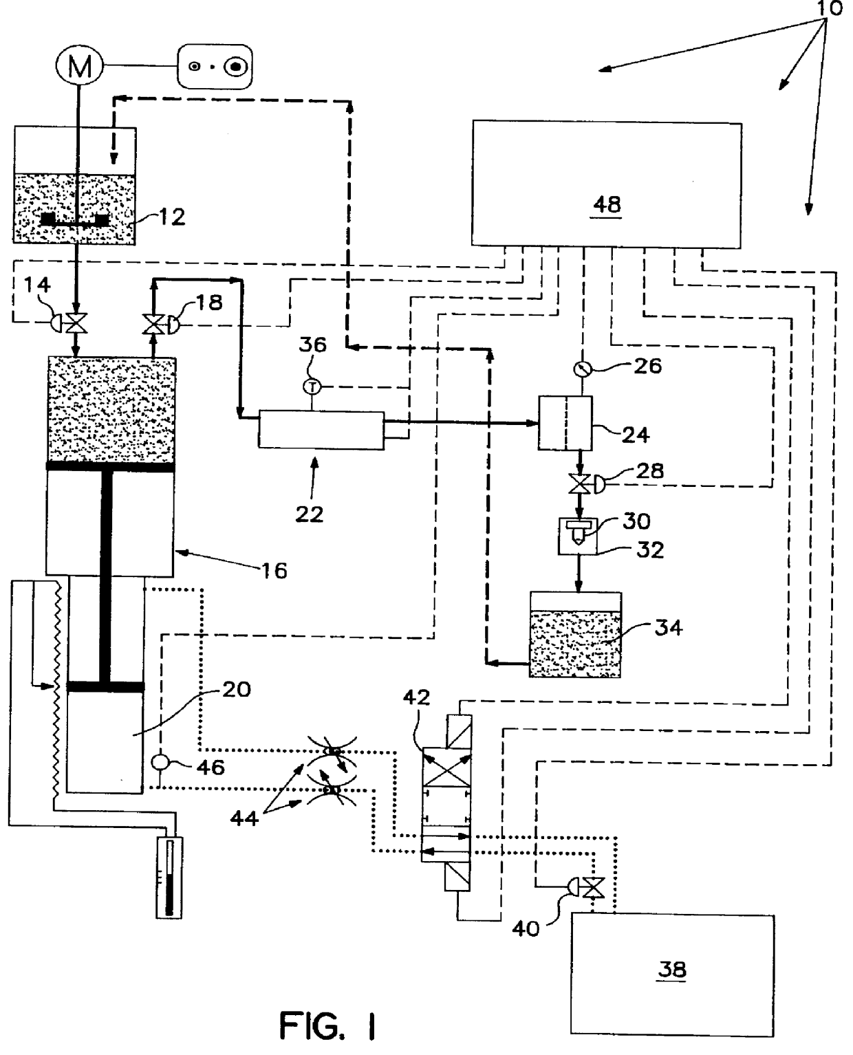
Referring to FIG. 1, the system is shown generally at 10 and comprises an inlet tank 12 with an associated valve 14. The inlet tank 12 communicates with a slurry cylinder 16 having an associated valve 18. A hydraulic cylinder 20 communicates with and drives the slurry from the cylinder 16. The slurry flows through a Coriolus flow meter 22. Downstream of the flow meter 22 is a filter 24 with an associated pressure transducer 26. A dispensing valve 28 is downstream of the filter 24 which in turn is upstream of a fixture 32. A nozzle 30 is secured in the fixture 32. The slurry flowing through the nozzle 30 is discharged into an outlet tank 34. Alternatively, the slurry can be recycled back to the inlet tank 12. Also, for general data collection purposes there is a temperature transducer 36.

A hydraulic power unit 38 in combination with a proportional control valve 40, a directional valve 42 and flow control valves 44, drives the hydraulic cylinder 20 to maintain constant pressure of th...


PUM

PropertyMeasurementUnit
pressureaaaaaaaaaa
areaaaaaaaaaaa
diameteraaaaaaaaaa

Abstract

A system and method for radiusing and sizing microholes in diesel fuel injectors. A liquid abrasive slurry with rheological properties is used. As the slurry approaches and flows through the microhole, it is at first at a lower viscosity. Subsequently, the slurry is characterized by a high viscosity which enables the use of a flow meter in the slurry flow path which directly and accurately monitors slurry flow rate and mass flow in real time. This allows for the individual slurry processing of nozzles to their specified flow rate in a continuous process.

Description

This invention relates to the use of an abrasive liquid slurry to radius and smooth a microhole.BACKGROUND AND BRIEF SUMMARY OF THE INVENTIONIn many applications, such as fuel injector nozzle tips, carburetor jets, cooling air flow through turbine engine components, lubricating oil metering for precision bearings and the like, metering of flow rates is of very great importance. However, due to manufacturing artifacts, it is of great difficulty. Even minute variations in manufacturing tolerances can produce substantial variations in flow resistance and flow.Parts having fluid flow orifices are made by a wide variety of casting and machining procedures. For example, high quality investment castings are frequently employed for the manufacture of such parts. Even the high quality parts will have variations in dimensions, particularly wall thicknesses attributable to slight core misalignments or core shifting, and other variations in surface conditions, including surface roughness, pits,...

Claims


Application Information

Patent Timeline
Patent Type & Authority Patents(United States)
IPC IPC(8): B24B31/00B24B31/116B24B49/02F02M61/00F02M61/16F02M61/18
CPCB24B31/116F02M61/1806F02M61/168B24B49/02
Inventor PERRY, WINFIELD B.
Owner EXTRUDE HONE CORP
Why Eureka
Try Eureka