Coated tool of cemented carbide

a cemented carbide and tool technology, applied in the direction of instruments, superimposed coating process, other chemical processes, etc., can solve the problems of reducing the breakage resistance of the tool, reducing the breakage resistance, so as to improve the breakage resistance and wear resistance, and prolong the tool life.

Inactive Publication Date: 2001-02-13
SUMITOMO ELECTRIC IND LTD
View PDF10 Cites 61 Cited by
  • Summary
  • Abstract
  • Description
  • Claims
  • Application Information

AI Technical Summary

Benefits of technology

In order to achieve the above described object, the inventors have made various studies and consequently, have found that using a cemented carbide alloy consisting of a matrix of WC and a binder phase of an iron group metal, a ceramic film having a specified film quality and structure is coated onto its surface and the lengths and intervals of cracks introduced into the coated film are precisely controlled by a thermal or mechanical procedure, whereby to improve both the properties of a breakage resistance and wear resistance and to lengthen the tool life to a great extent. That is, the present invention comprises specified inventions or embodiments summarized below:

Problems solved by technology

In such CVD coated cemented carbide tools, there arises a problem that a tensile residual stress occurs in the coated film during cooling after the coating due to difference in coefficient of thermal expansion between the coated film and substrate, and the breakage resistance of the tool is thus lowered.
In this proposed method, it is confirmed that the breakage resistance can be improved to some extent, but because of previously introducing cracks into the coated film to be penetrated therethrough to the substrate, Griffith' precrack length is increased, thus resulting in lowering of the breakage resistance, wear fluctuation of the coated film and deterioration of the wear resistance from the longer cracks.
As described above, the coated cemented carbide tools of the prior art have the problems that when the thickness of a coated film is increased to improve the wear resistance, the breakage resistance of the tool is decreased and even when cracks are previously introduced into a coated film with a relatively large thickness, the wear resistance is rather lowered depending on the cracked state.
These problems have not been solved yet.

Method used


Image

  • Coated tool of cemented carbide
  • Coated tool of cemented carbide
  • Coated tool of cemented carbide

Examples


example 2

An insert of the same cemented carbide having a Form No. ISO and a shape of CNMG 120408 as that of Example 1 was prepared. This insert was coated with Coated Film Quality 3 described in Example 1 and subjected to a blasting treatment of the surface of the coated cemented carbide using iron powder of about 100 .mu.m in grain size from the rake face side while changing a projection speed of the iron powder to prepare various inserts differing in cracked state in the coated film, as shown in Table 3. Using these inserts, the same cutting test as that of Example 1 was carreid out.

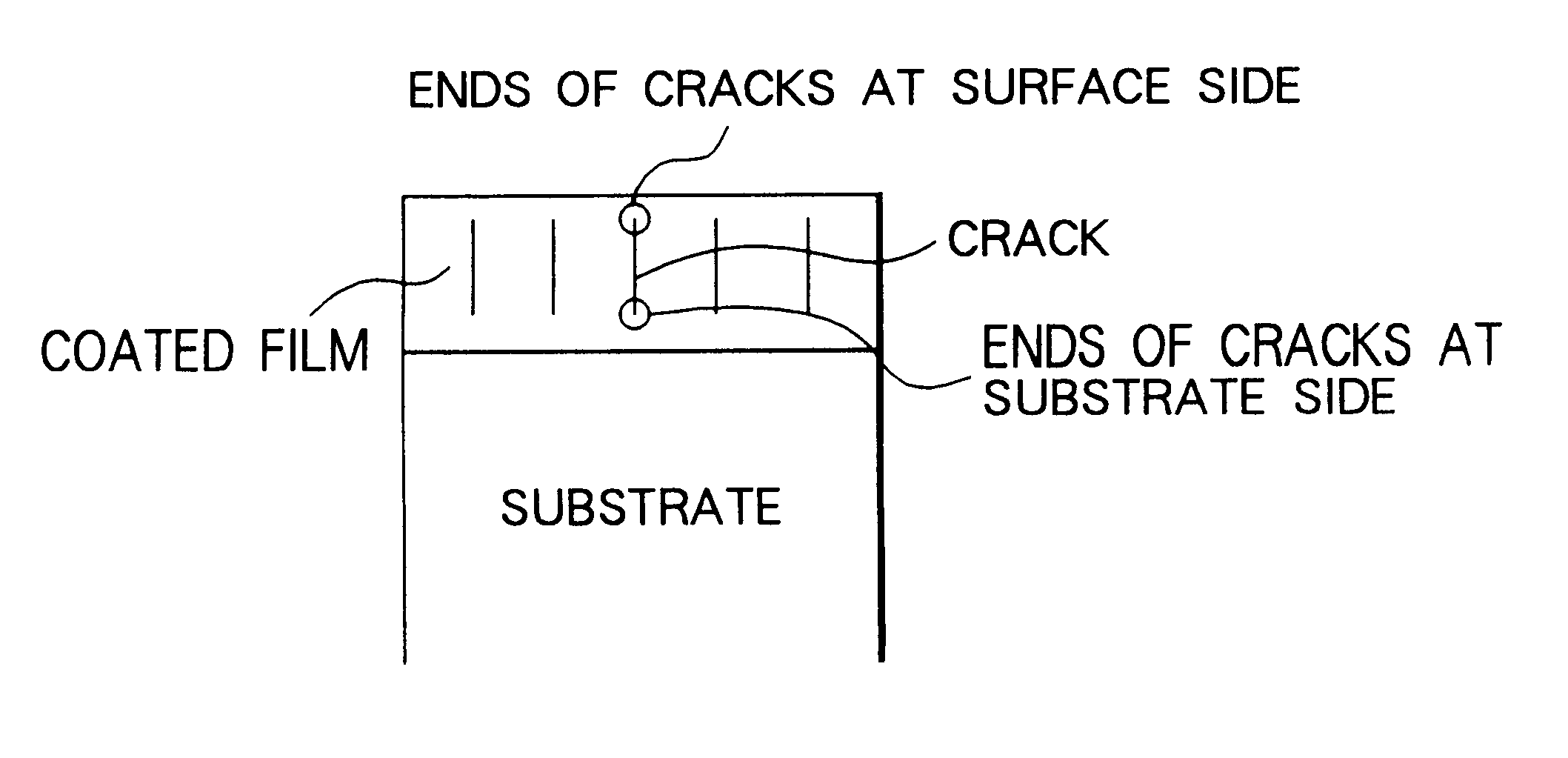
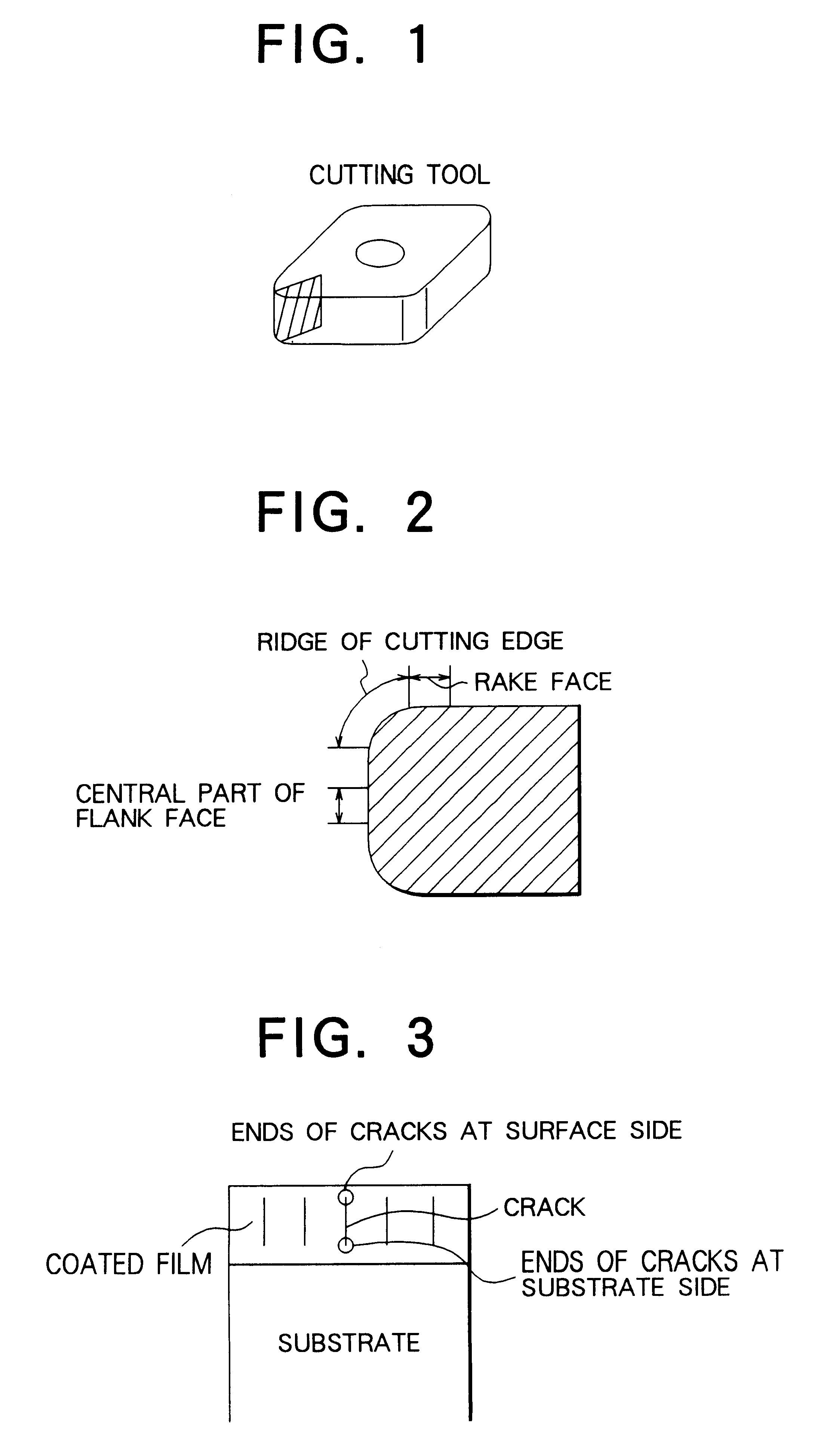
The results are shown in Table 4. The inserts of Sample Nos. 2-3 to 2-7 within the scope of the present invention all exhibit excellent breakage resistance and wear resistance and above all, Sample Nos. 2-5, 2-6 and 2-7, in which such a proportion that the ends of cracks, at the substrate side, in the coated film on the ridge of the cutting edge are terminated in the innermost titanium nitride layer and titaniu...

example 3

An insert of the same cemented carbide having a Form No. of ISO and a shape of CNMG 120408 as that of Example 1 was prepared. This insert was then coated with the following Coated Film Quality 4 in order from the lower layer:

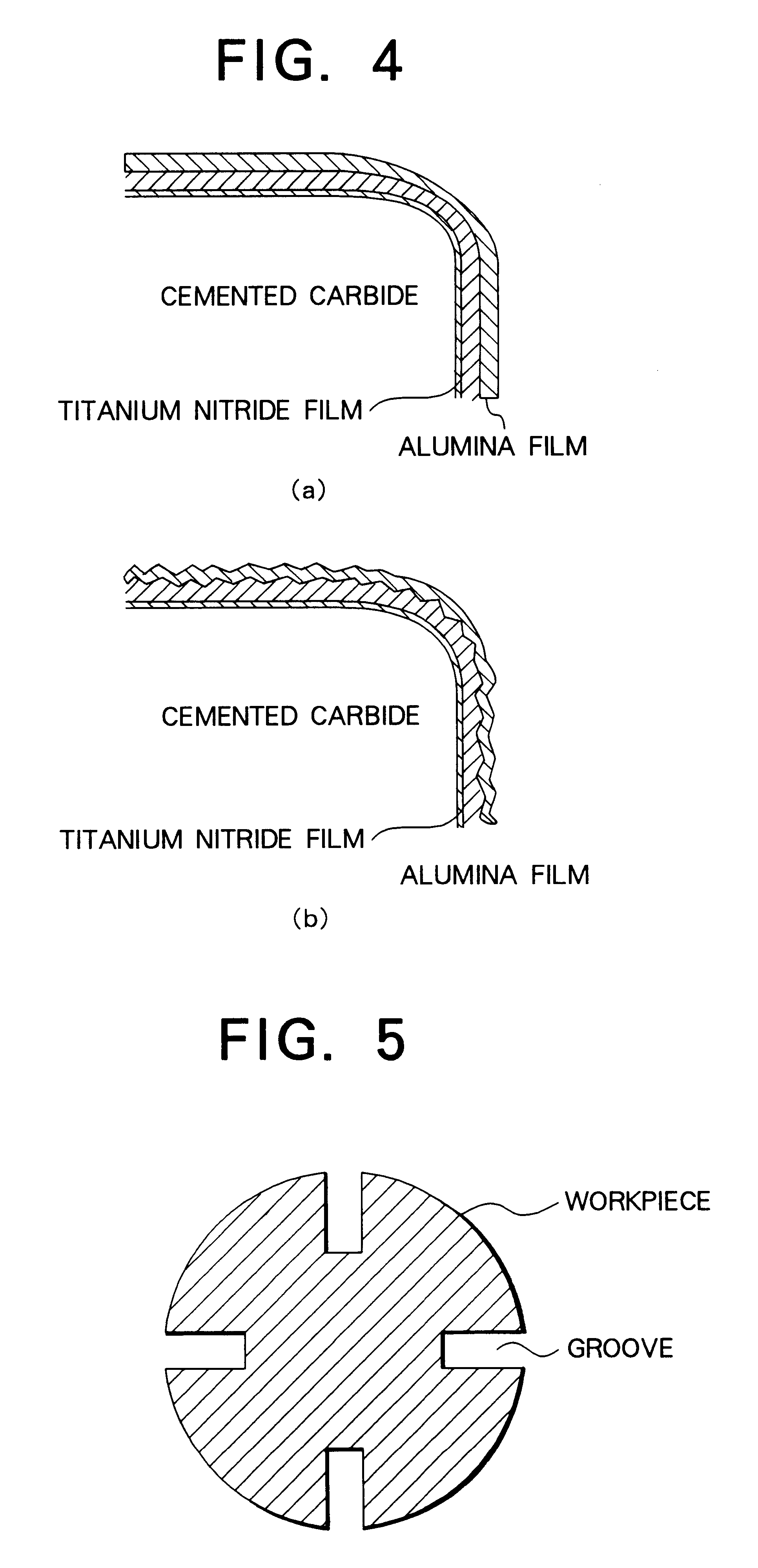
Film Quality 4: 1 .mu.m TiN-7 .mu.m TiCN (aspect ratio 5.about.20)-2 .mu.m TiC-5 .mu.m .kappa.-alumina (total film thickness 15 .mu.m)

The TiCN film was prepared by effecting the coating using acetonitrile, nitrogen gas, TiCl.sub.4 and hydrogen gas as a starting gas or carrier gas, while varying the coating temperature within a range of 800 to 1000.degree. C. during the coating and further varying the pressure in a furnace and gas composition to obtain an aspect ratio 5.about.20. In addition, the flank face of each sample of the resulting tools was masked and then was subjected to a blasting treatment with an iron powder from the rake face side while changing a projection speed of the iron powder to prepare various inserts differing in cracked state in the coated...

example 4

A cemented carbide powder with a composition comprising, by weight, 86% WC-1% TaC-1% NbC-3% TiC-2% ZrCN-7% Co was pressed, sintered in vacuum at 1400.degree. C. for 1 hour and subjected to a surface grinding treatment and cutting edge treatment to prepare a cemented carbide insert with a Form No. ISO and a shape of CNMG 120408. When a cross section of this cemented carbide was mirror-polished and its microstructure was observed by an optical miscroscope, it was confirmed that there could be formed a .beta.-free layer of about 25 .mu.m in thickness on the alloy surface and an area with a higher hardness an inside the alloy directly below the .beta.-free layer. This insert and the insert having no .beta.-free layer on the alloy surface, prepared in Example 1, were coated with Film Quality 3 coated in Example 1.

Furthermore, the surface of this coated cemented carbide was subjected to a blasting treatment using an iron ball in an analogous manner to Example 1, while changing the size, p...


PUM

PropertyMeasurementUnit
thicknessaaaaaaaaaa
thicknessaaaaaaaaaa
thicknessaaaaaaaaaa

Abstract

The principal object of the present invention is to provide a coated cemented carbide tool whose both properties of breakage resistance and wear resistance are improved and whose life is lengthened.The present invention has been made to achieve this object and is related with a coated cemented carbide cutting tool comprising a substrate consisting of a matrix of WC and a binder phase of an iron group metal and a plurality of coated layers provided on a surface of the substrate, in which (a) an innermost layer, adjacent to the substrate, of the coated layers consists essentially of titanium nitride having a thickness of 0.1 to 3 mum, (b) on a mirror-polished cross-sectional microstructure of the said tool, an average crack interval in the coated film on a ridge of a cutting edge and/or rake face is smaller than an average crack interval in the coated layer on a flank face, (c) at least 50% of the cracks in the coated film on the said ridge of the cutting edge and/or rake face have ends of the cracks in the said innermost titanium nitride layer, in a layer above the titanium nitride layer or in an interface between these layers and (d) an average crack length in the coated film on the said ridge of the cutting edge and/or rake face is shorter than an average film thickness on the flank face.According to the present invention, quantitatively specifying the crack intervals and positions of the ends of the cracks in the coated layer results in excellent breakage resistance as well as wear resistance.

Description

This invention relates to a cutting tool, in particular, which is most suitable as a coated cemented carbide cutting tool used for cutting steels and cast irons and which is excellent in wear resistance as well as breakage resistance.BACKGROUND TECHNIQUEHitherto, cemented carbides (WC-Co alloys or WC-Co alloys to which carbonitrides of Ti, Ta or Nb are added) have been used as a tool material for cutting metallic materials. However, as cutting speeds have lately been increased, a tendency of using cemented carbide tools comprising cemented carbide substrates coated with coated films consisting of carbides, nitrides, carbonitrides, carboxides, boronitrides or oxides of Group IVa, Va and VIa elements of the Periodic Table or Al or their solid solutions by CVD or PVD methods in a thickness of 3 to 15 .mu.m is enhancing. The thickness of the coated films tends to further increase and CVD coated cemented carbides with a coating thickness of at least 20 .mu.m have been proposed. In such C...

Claims


Application Information

Patent Timeline
Patent Type & Authority Patents(United States)
IPC IPC(8): C23C30/00
CPCC23C28/044C23C30/005Y10T428/265Y10T407/27Y10T428/24975B23B27/14
Inventor MORIGUCHI, HIDEKIIKEGAYA, AKIHIKOYAMAGATA, KAZUO
Owner SUMITOMO ELECTRIC IND LTD
Why Eureka
Try Eureka