

Method of purifying exhaust gas and catalyst for purifying exhaust gas
a technology of exhaust gas and catalyst, which is applied in the direction of catalyst activation/preparation, physical/chemical process catalyst, separation process, etc., can solve the problems of inactive reduction reactions of purifying no.sub.x, large amount of oxygen, and inferior adsorption force of noble metal in the catalys
- Summary
- Abstract
- Description
- Claims
- Application Information
AI Technical Summary
Benefits of technology
Problems solved by technology
Method used
Image

Examples
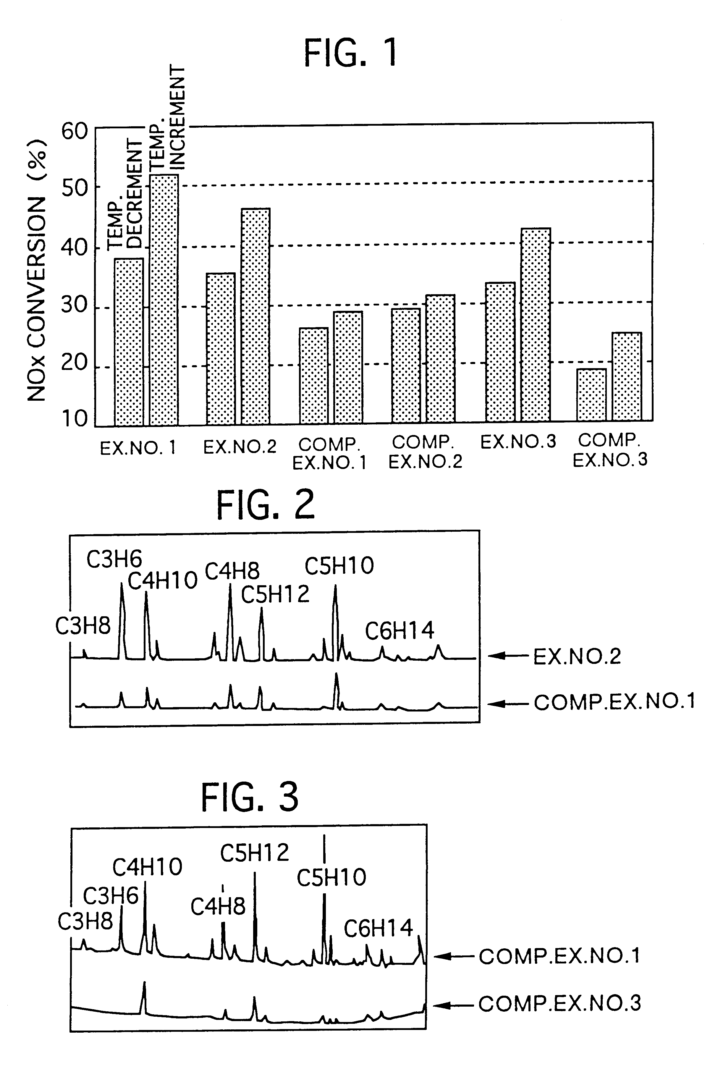
example no.2
EXAMPLE NO. 2
First, the aforementioned mordenite, the aforementioned alumina sulfate powder with Pt loaded, a cerium-zirconium composite oxide with Pt loaded, the aforementioned silica sol, and pure water were prepared.
Here, the cerium-zirconium composite oxide was prepared by mixing 172 g of ceria and 123 g of zirconia and by burning this mixture at 600.degree. C. for 1 hour. This cerium-zirconium composite oxide also comprised Ce and Zr in a molar ratio of 1:1. Then, on this cerium-zirconium composite oxide, Pt was loaded in the same manner as described above, thereby obtaining the cerium-zirconium composite oxide with Pt loaded.
In Example No. 2, these were mixed in proportions set forth in Table 2, thereby preparing a slurry.
Thereafter, in the same manner as Example No. 1, a loading layer was formed on the aforementioned support substrate. Thus, a catalyst of Example No. 2 was obtained.
example no.3
EXAMPLE NO. 3
First, the aforementioned mordenite, zirconia sulfate with Pt loaded and working as the solid strong acid, the aforementioned cerium-zirconium composite oxide with Pt loaded, the aforementioned silica sol, and pure water were prepared.
Here, zirconia sulfate is prepared by treating a zirconia powder with 1N sulfuric acid, and thereafter by drying it at 100.degree. C. for 1 hour, and by burning it at 600.degree. C. for 1 hour. And, Pt was loaded in the same manner as described in the aforementioned manner, thereby obtaining the zirconia sulfate with Pt loaded and working as the solid strong acid.
Moreover, on the cerium-zirconium composite oxide, Pt was loaded in the same manner as described above.
In Example No. 3, these were mixed in proportions set forth in Table 5, thereby preparing a slurry.
Thereafter, in the same manner as Example No. 1, a loading layer was formed on the aforementioned support substrate. Thus, a catalyst of Example No. 3 was obtained.
example no.4
EXAMPLE NO. 4
First, a zirconium hydroxide powder was mixed in 1N sulfuric acid aqueous solution, was suction-filtered, was thereafter dried at 120.degree. C. for 1 hour, was burned at 500.degree. C. for 1 hour to prepare a strongly-acidified powder, and was made into a slurry. And, a honeycomb support substrate was used on which a coating layer similar to that of Comparative Example No. 4 was formed, the aforementioned strongly-acidified powder made into the slurry was coated, was dried at 120.degree. C. for 1 hour, was thereafter burned at 500.degree. C. for 1 hour.
Next, a dinitrodiammine platinum nitrate aqueous solution having a predetermined concentration was prepared, and the resulting honeycomb support substrate was entirely immersed therein for 1 hour. Thereafter, the honeycomb support substrate was taken up therefrom to blow off the excessive water droplets, was dried at 120.degree. C. for 1 hour, and thereafter was burned at 300.degree. C. for 1 hour, thereby uniformly load...
PUM
| Property | Measurement | Unit |
|---|---|---|
| molar ratio | aaaaa | aaaaa |
| molar ratio | aaaaa | aaaaa |
| silicon-to- | aaaaa | aaaaa |
Abstract
Description
Claims
Application Information