
Optical filters

Inactive Publication Date: 2001-03-06
BRITISH TELECOMM PLC +1
View PDF20 Cites 43 Cited by
  • Summary
  • Abstract
  • Description
  • Claims
  • Application Information

AI Technical Summary

Benefits of technology

The in-line filter of the present invention may with advantage be integrated within an active device such as a semiconductor laser to provide a compact and tunable optical source.
This aspect of the present invention provides a novel structure for a GAVCF device. Conventionally, the grating in a GAVCF has been etched above, below or into the stronger waveguide. The device of the present invention, by contrast, uses a grating which is formed laterally about the waveguide. This produces a structure which is easier to fabricate and provides enhanced yields.

Problems solved by technology

While a tuning range as broad as 40 nm has been claimed for such a device, it has the disadvantages of being complicated to fabricate and to control.
Although a tuning range of 70 nm is claimed, and only one control current is required, the device is not able to cover all wavelengths but hops between longitudinal modes of the laser cavity.

Method used


Image

  • Optical filters
  • Optical filters
  • Optical filters

Examples


Embodiment Construction

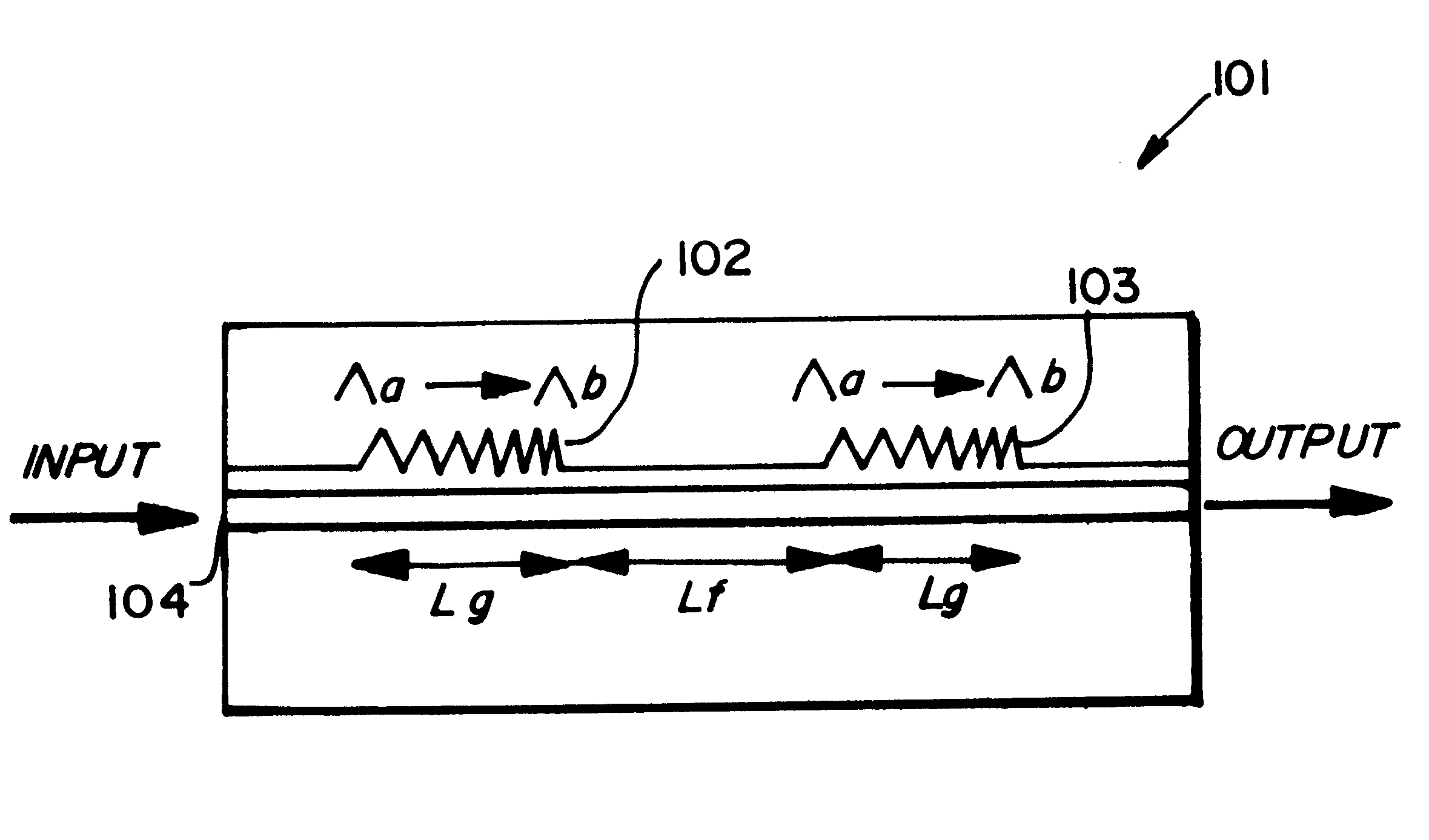
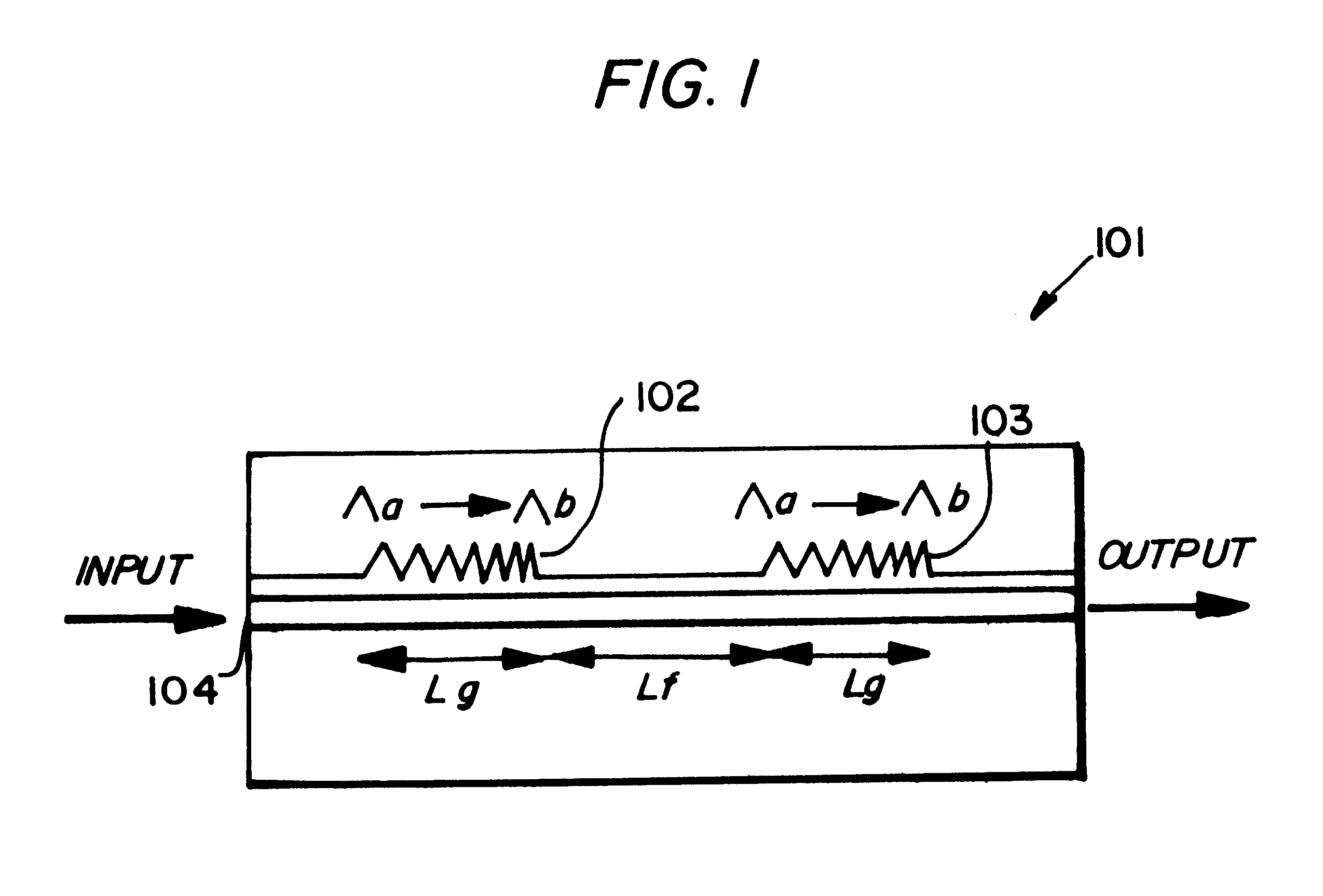
As shown in FIG. 1, an optical filter 101 comprises a pair of superstructure gratings (SSG's) 102, 103, each of length L.sub.g with a flat region of length L.sub.f between them, giving a total cavity length of L.sub.f +2L.sub.g. The grating pitch changes from .LAMBDA..sub.a to .LAMBDA..sub.b to give equally spaced longitudinal modes from .lambda.a (=2n.sub.eq.LAMBDA..sub.8 / n, where N.sub.eq is the equivalent refractive index and n is the grating order) to .lambda.b (=2n.sub.eq.LAMBDA..sub.b / n). The gratings formed on the top surface of a waveguide layer 104 using electron beam lithography. This structure termed by the invertors as In-Line Fabry-Perot (ILFP) produces a comb-filter response as seen, for example, in FIG. 3.

The dimensions, materials and process of manufacture for the filter are described in further detail below with reference to the GAVCF laser.

As an alternative to the use of a chirped grating, the filter may be constructed using a multi-phase-shifted grating [H. Ishi...


PUM


Abstract

An optical filter is formed from at least two grating located in a waveguide region of a semiconductor optical device. Each grating has a multiple peak optical passband. The gratings are spaced apart in the waveguide region and form an optical cavity having a comb-filter characteristic. The gratings may be located in the active region of an optical gain element and in a preferred example are superstructure gratings (SSGs). A number of filters may be joined together in series.

Description

1. Field of the InventionThe present invention relates to optical filters, and to optical sources incorporating such filters. In particular it relates to tunable filters and sources suitable for us, for example, in optical networks employing wavelength division multiplexing (WDM).2. Related ArtThe use of WDM and wavelength routing in optical networks has been proposed to provide the increased bandwidth required, for example, for the provision of multimedia services. Tunable lasers and filters are essential components for the implementation of such systems and desirably should provide tuning ranges of around 40 nm to allow complete coverage of the erbium amplifier transmission window around 1550 nm, for example.It has previously been proposed to use a distributed Bragg reflector laser (DBR) as a tunable source [Oeberg M et al., "Complete single mode wavelength coverage over 40 nm with a super structure grating DBR laser" 14th Semi. Laser Conf. Proceedings, 1994, pp32-33]. While a tun...

Claims


Application Information

Patent Timeline
IPC IPC(8): G02B6/124G02B6/12H01S5/0625H01S5/10H01S5/00H01S5/50H01S5/323H01S5/12
CPCG02B6/12007G02B6/124H01S5/06258H01S5/1032H01S5/06256H01S5/1035H01S5/1209H01S5/1218H01S5/1225H01S5/124H01S5/32391H01S5/5045
Inventor LEALMAN, IAN FROBERTSON, MICHAEL JOKAI, MAKOTO
Owner BRITISH TELECOMM PLC
Features
  • Generate Ideas
  • Intellectual Property
  • Life Sciences
  • Materials
  • Tech Scout
  • Unparalleled Data Quality
  • Higher Quality Content
  • 60% Fewer Hallucinations
Learn More