Brazed honeycomb collimator

a collimator and honeycomb technology, applied in the field of honeycomb collimators, can solve the problems of excessive blockage of sputtered atoms traveling, large amount of waste material, and high production cos

Inactive Publication Date: 2001-09-11
INNOVENT
View PDF39 Cites 41 Cited by
  • Summary
  • Abstract
  • Description
  • Claims
  • Application Information

AI Technical Summary

Problems solved by technology

Machined collimators produce a relatively large amount of waste material, tend to be relatively heavy due to required minimum wall thickness between adjacent apertures, and are costly to produce due to the extensive machining operation.
Further, the ratio of collimator passage open area to unmachined area between the passages is relatively low, resulting in excessive blockage of sputtered atoms traveling along otherwise acceptable normal and near normal trajectories.
Such collimators, however, also tend to be relatively heavy, costly to produce, and generate imprecise collimator passage geometries.
While such welded collimators may be lighter and produce less blockage than machined collimators, a contamination problem exists inherently due to the manufacturing process.
Such contaminants render a certain percentage of the devices on the wafer and subsequently processed wafers unusable, negatively impacting process yields and increasing cost per device.
Further, welded collimators produce gaps or voids in the nodes due to locally irregular geometries of the wall sections which are neither perfectly flat nor perfectly mated.
Because of these voids, foreign matter introduced during the manufacturing process may become trapped in the nodes.
Residual contaminants typically remain trapped in the voids in the nodes.

Method used


Image

  • Brazed honeycomb collimator
  • Brazed honeycomb collimator
  • Brazed honeycomb collimator

Examples


example 1

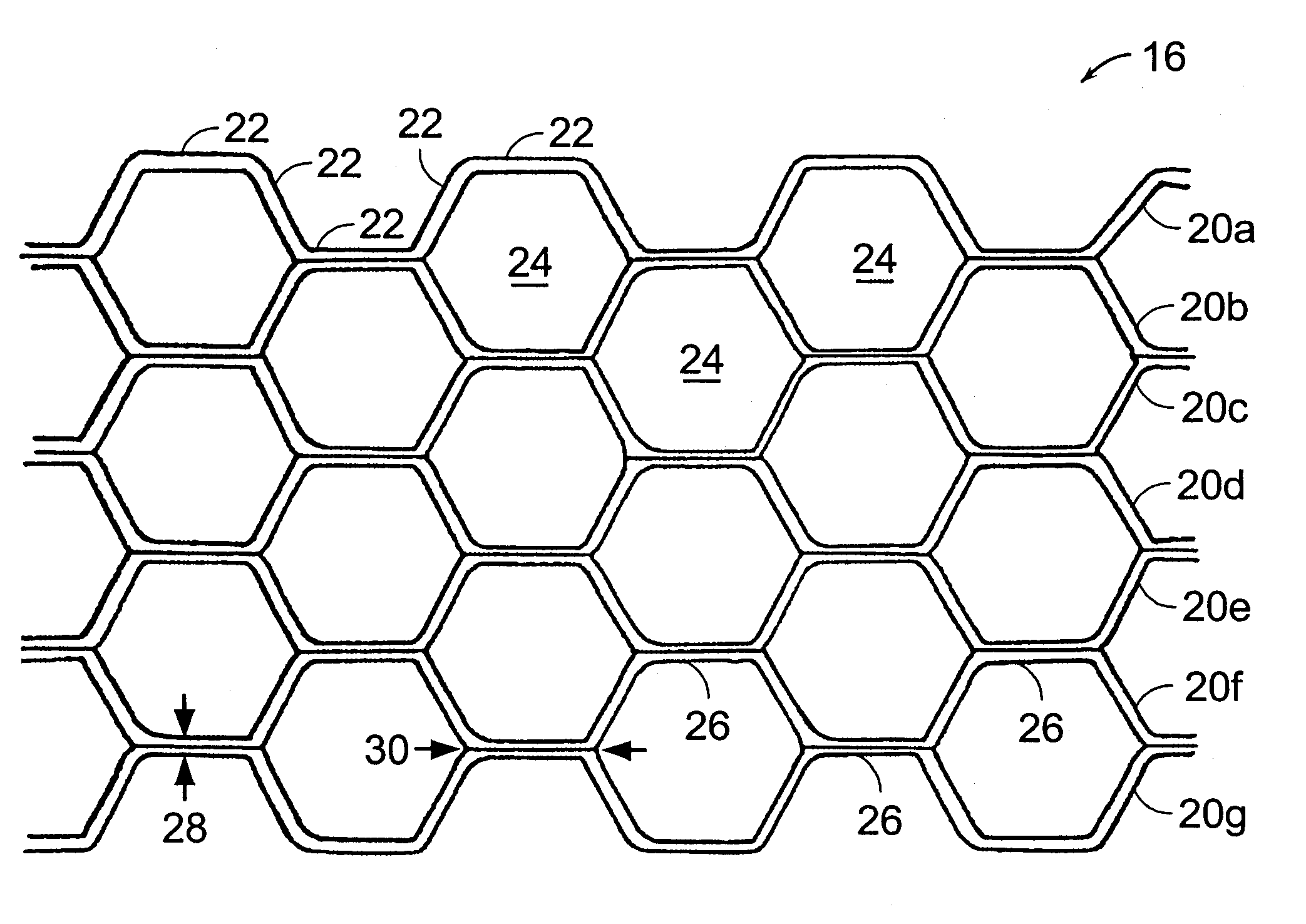
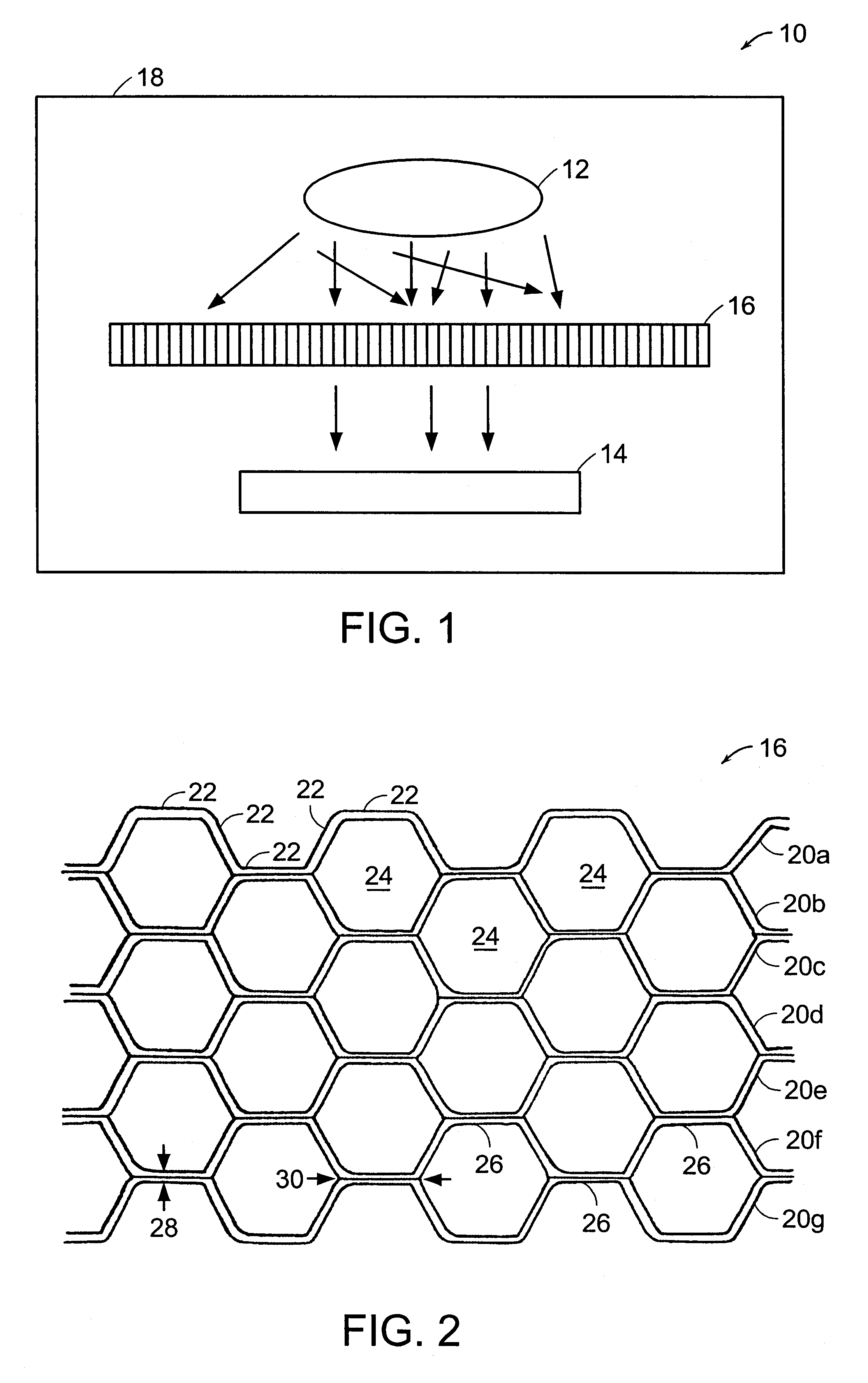
A collimator was manufactured from stainless steel 316L material (0.03C-2.0Cr-1.0Si16 / 18Cr-10 / 14Ni-0.045P-0.03S) by resistance spot welding corrugating ribbons to created a nested honeycomb pattern substantially similar to that depicted in FIG. 2. The ribbons were formed from 0.038 cm (0.015 inch) thick stock having a width of about 1.59 cm (0.625 inches). After welding, the collimator was cleaned by soaking first in acetone, then in alcohol, followed by air drying. AMS 4782 E, Mesh 140, braze powder (Ni71, Cr19, Si10) available from Wall Colmony Corporation located in Madison Heights, Michigan was mixed with Nicrobraz S binder, also available from Wall Colmony Corporation, in the recommended 10:1 ratio to form a thick slurry. The slurry was manually applied to the diverging wall portions of the collimator by extrusion through a syringe with a tip diameter of about 0.083 cm (0.033 inches). The binder was allowed to air dry. No flux was used due to the possibility of interaction with...

example 2

A collimator was manufactured from titanium CP Grade 4 material (Ti, <0.4O, <0.5Fe) by resistance spot welding corrugating ribbons to created a nested honeycomb pattern substantially similar in configuration to that discussed in Example 1. TiCu15Ni15 braze powder available from WESGO Metals Division located in Melrose, Massachusetts was mixed with Nicrobraz S or Vitta FC 15 binders, the latter available from Vitta Corporation located in Bethel, Connecticut, in the recommended 3:1 ratio to form thick slurries. The slurries were manually applied to the diverging wall portions of several collimators by extrusion through a syringe.

The vacuum furnace and graphite fixturing were prepared by loading the fixturing into the furnace, sealing the furnace, and pumping the furnace down to below about 5.times.10.sup.-4 Torr vacuum. The furnace was heated to about 1260.degree. C. (2300.degree. F.) at a rate of about 11 to 17.degree. C. / min (20 to 30.degree. F. / min) and held at temperature for abou...

example 3

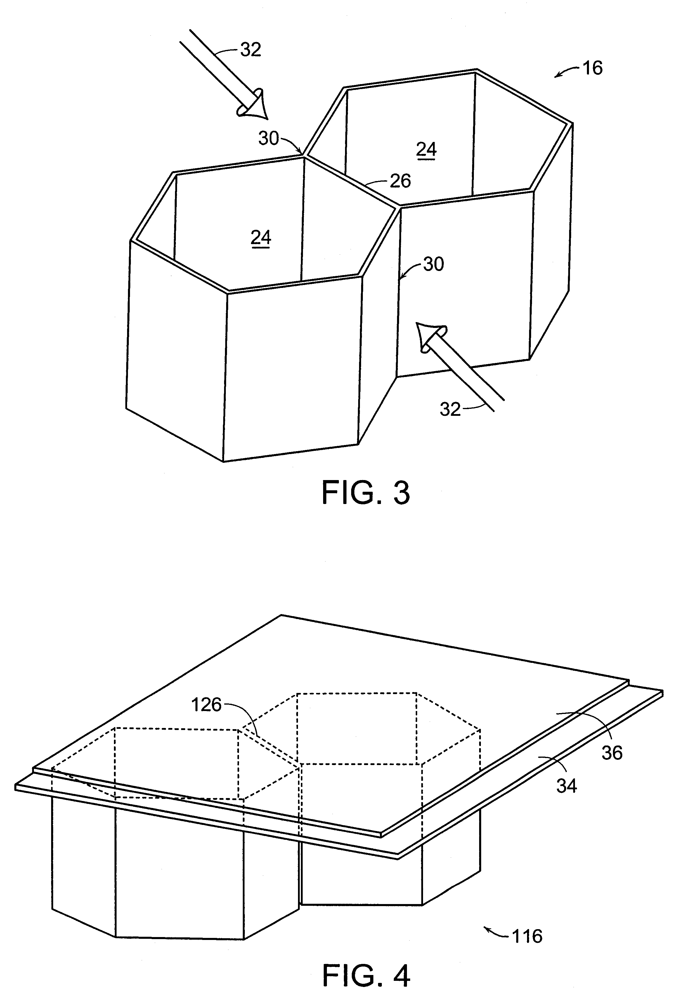
A stainless steel collimator similar to that discussed in Example 1 was prepared for brazing by application of the braze material using a Binks Model 180 spray gun available from Binks Manufacturing Company located in Franklin Park, Illinois. AMS 4782 E, Mesh 140, braze powder and Nicrobraz 520 binder, also available from Wall Colmony Corporation, were added to the appropriate containers in the spray gun. The gun was adjusted to exhibit a pattern of binder and alloy on a smooth surface wherein the alloy sticks to the surface without excessive wetting by the binder which would cause the braze material to run when applied to a vertical surface. The collimator was sprayed in several passes along the ribbon direction with the spray gun held at about a 45 degree angle as discussed hereinabove with respect to FIG. 3. The collimator was inverted and the process repeated. The collimator was weighed before and after application of the braze material to quantify the average weight of braze ma...


PUM

PropertyMeasurementUnit
temperaturesaaaaaaaaaa
included angleaaaaaaaaaa
angleaaaaaaaaaa

Abstract

A collimator filter for a physical vapor deposition apparatus useful for coating semiconductor wafers includes a plurality of corrugated ribbons attached at abutting double-walled nodes by resistance spot welding. The nodes are sealed by application of a braze material to diverging wall portions of the nodes by extrusion or spraying, followed by heating in a vacuum furnace. Alternatively, the nodes may be sealed by application of a braze material foil to a top and a bottom surface of the collimator followed by heating in the vacuum furnace. By sealing the nodes, a significant reduction may be achieved in outgassing and generation of particulate contaminants.

Description

The present invention relates to physical vapor deposition ("PVD") apparatus for coating articles and more particularly to an improved method of manufacturing a collimator filter used in PVD processing of semiconductor wafers.BACKGROUND INFORMATIONA PVD process may be used to deposit a target material such as titanium or titanium nitride onto a semiconductor wafer or other article. In a typical PVD apparatus, the target material and the article to be coated are disposed in a vacuum chamber containing an inert gas such as argon. An electrically conductive shield is generally provided circumscribing the target and the article. Upon application of a sufficiently high electrical potential between the cathodic target and the anodic shield, the inert gas ionizes, forming a high energy plasma. Relatively high mass, positively charged plasma ions impinge the negatively charged target with sufficient energy to expel atoms from the target, forming a physical vapor. The expelled or sputtered t...

Claims


Application Information

Patent Timeline
Patent Type & Authority Patents(United States)
IPC IPC(8): C23C14/56C23C14/34
CPCC23C14/34C23C14/564H01J37/3447Y10T428/24149Y10T428/24165
Inventor PELLETIER, DOMINIC GERARDKRAUSKOPF, NISGREGORY, SCOTT JAMES
Owner INNOVENT
Why Eureka
Try Eureka