
Method for forming an L-shaped spacer with a disposable organic top coating

a technology of organic top coating and spacer, which is applied in the manufacture of semiconductor/solid-state devices, electrical devices, transistors, etc., can solve the problems of affecting the shape and size of the spacer, the top oxide portion of the spacer cannot be easily removed without damaging the oxide isolation structure, and the spacer is inconsistent across the ic and between the i

Inactive Publication Date: 2001-09-25
CHARTERED SEMICONDUCTOR MANUFACTURING
View PDF13 Cites 25 Cited by
  • Summary
  • Abstract
  • Description
  • Claims
  • Application Information

AI Technical Summary

Benefits of technology

It is another object of the present invention to provide a method for forming an L-shaped spacer that has a reduced susceptibility to post-etch wet chemical processing.
It is another object of the present invention to provide a method for forming an L-shaped spacer that provides for better gap filling properties of the subsequently formed, overlying dielectric layer.
It is yet another object of the present invention to provide a method for forming an L-shaped dielectric spacer with a reduced cycle time and a reduced thermal budget.
The present invention provides considerable improvement over the prior art. The sacrificial organic layer can be deposited in less time than an oxide layer, as is used in the prior art, reducing cycle time. The organic dielectric layer also requires a lower thermal budget to form than does an oxide layer. The spacer which results from the process of the present invention is less susceptible to post-etch wet chemical processing than an oxide layer, resulting in a more uniform spacers, both across the IC and between IC's. Because the sacrificial organic structure can be completely removed using a selective etch, the resulting L-shaped dielectric spacers are open and provide better gap filling properties of the subsequent dielectric layer (eg interlevel dielectric).

Problems solved by technology

The reduced space between gate electrodes can cause poor gap fill by the subsequent dielectric layer (eg inter-layer dielectric) resulting in degraded performance.
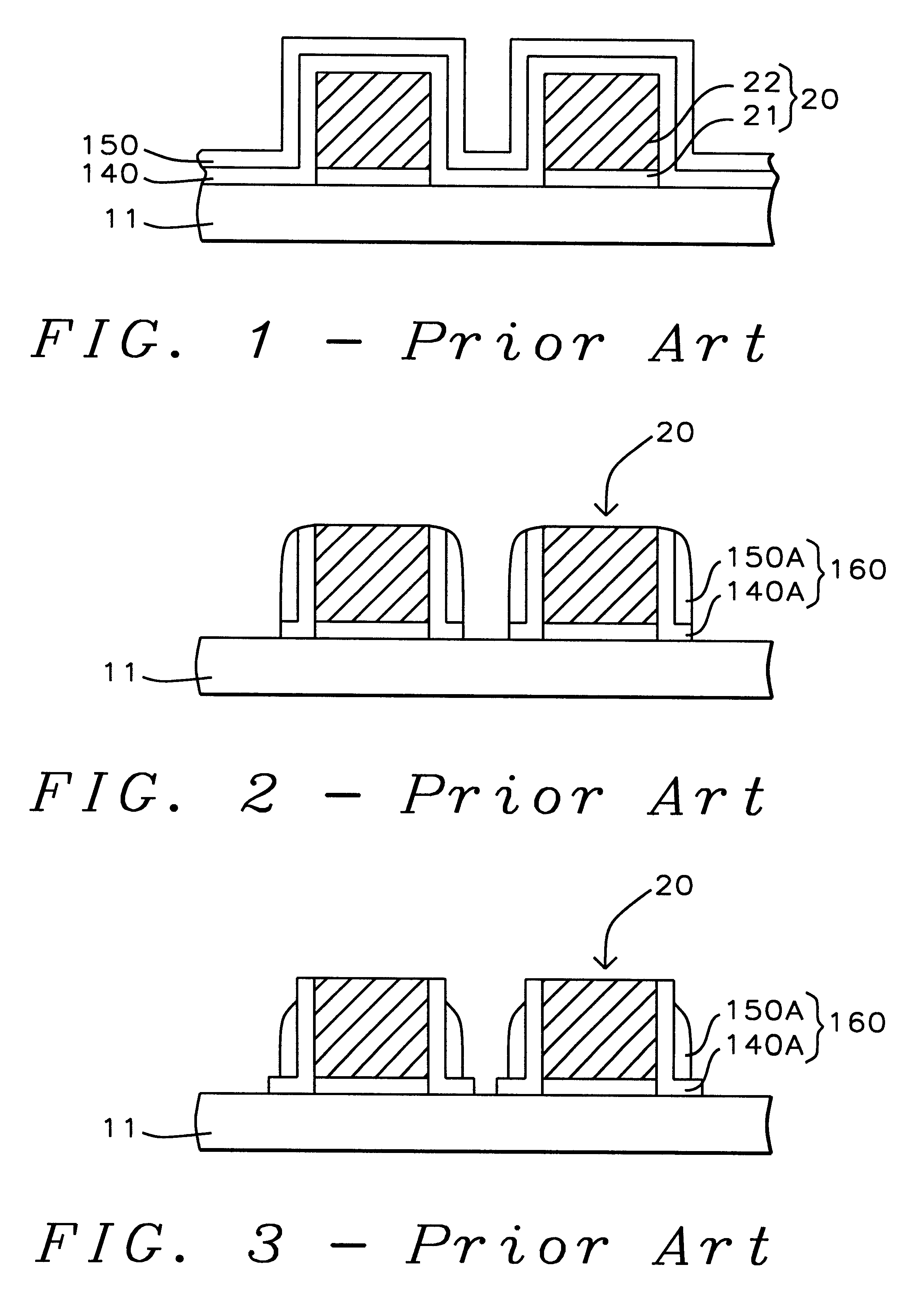
However, the top oxide portion of the spacer can not be easily removed without damaging oxide isolation structures.
Conversely, if the top oxide portion of the spacer remains, it can be effected by post-etch wet chemical process causing inconsistent spacer shape and size across the IC and between IC's.
Also, the gap filling ability of the subsequent dielectric layer is not optimized, because the aspect ratio remains high due to the presence of the oxide portion of the spacers.
One problem with this process identified by the inventors is that the remaining oxide layer (150) of the L-shaped spacer can not be easily removed using a selective oxide etch, because it would damage isolation structures which are typically used to isolate various active areas on an IC.
Variations in the shape and size of the L-shaped spacers results in inconsistent performance parameters for the transistor formed from the gates with the L-shaped spacers.

Method used


Image

  • Method for forming an L-shaped spacer with a disposable organic top coating
  • Method for forming an L-shaped spacer with a disposable organic top coating
  • Method for forming an L-shaped spacer with a disposable organic top coating

Examples


Embodiment Construction

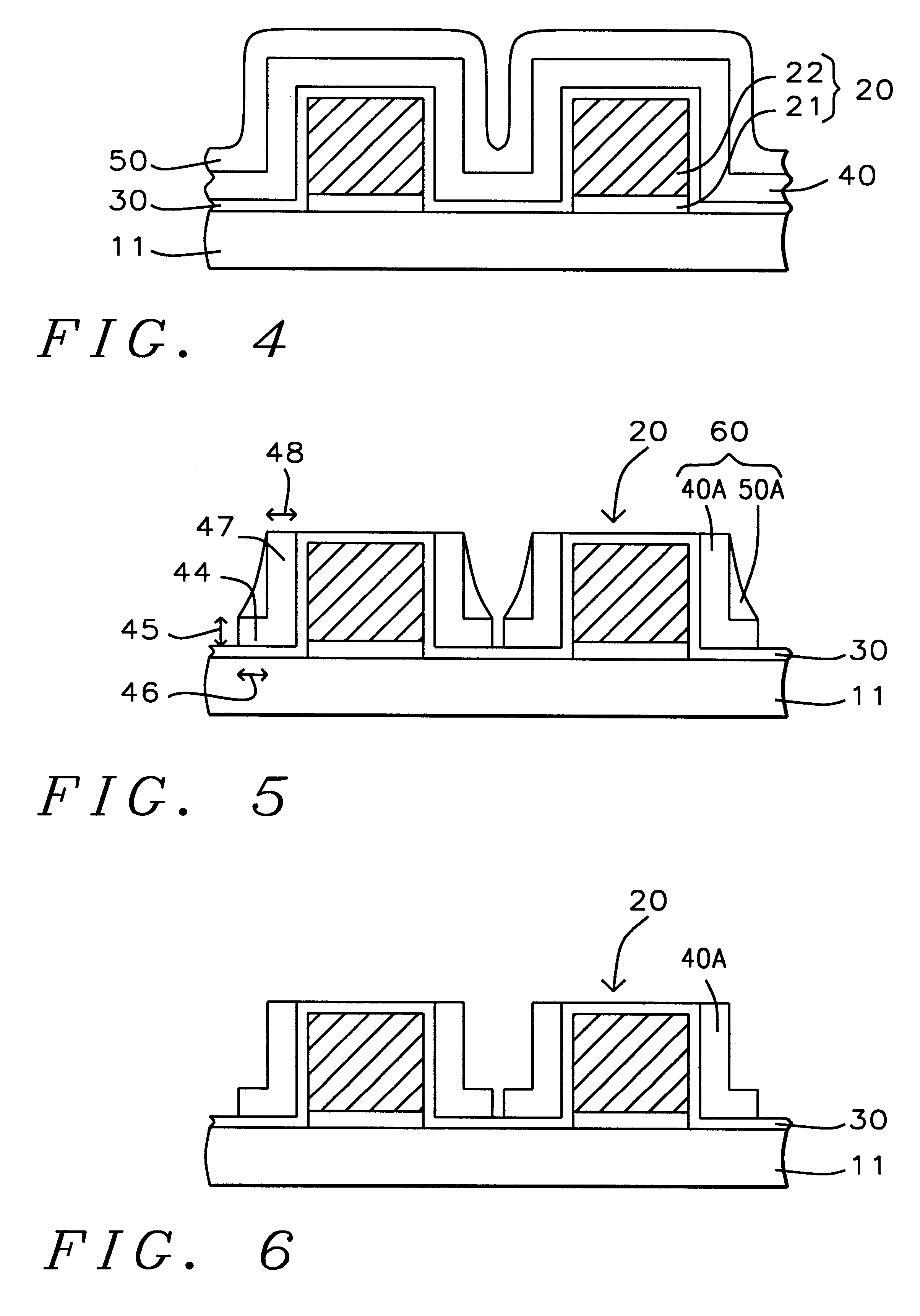
A preferred embodiment of the present invention is described with reference to FIGS. 4 through 6. The preferred embodiment provides a method for forming an L-shaped spacer using an organic top coat. The present invention provides a consistently controllable opening which is adequate for good gap-filling characteristics. Also, the organic top coat can be formed faster than an oxide layer using a lower thermal budget.

Referring to FIG. 4, the preferred embodiment of the present invention begins by providing a semiconductor structure (11). Semiconductor substrate (11) is understood to possibly include a substrate comprising a wafer of semiconductor material such as silicon or germanium or a like substrate structure such as silicon-on-insulator (SOI) as is known in the art. Semiconductor structure (11) should be understood to possibly further include one or more conductive and / or insulating layers and passive and / or active devices formed on or over said substrate. The semiconductor struc...


PUM


Abstract

A method for forming an L-shaped spacer using a sacrificial organic top coating. A semiconductor structure is provided having a gate structure thereon. A liner oxide layer is formed on the gate structure. A dielectric spacer layer is formed on the liner oxide layer. In the preferred embodiment, the dielectric spacer layer comprises a silicon nitride layer or a silicon oxynitride layer. A sacrificial organic layer is formed on the dielectric spacer layer. The sacrificial organic layer and the dielectric spacer layer are anisotropically etched to form spacers comprising a triangle-shaped sacrificial organic structure and an L-shaped dielectric spacer. The triangle-shaped sacrificial organic structure is removed leaving an L-shaped dielectric spacer.

Description

BACKGROUND OF INVENTION1. Field of the InventionThis invention relates generally to fabrication of a semiconductor device and more particularly to a method for forming an L-shaped spacer using a sacrificial organic top coating.2. Description of the Prior ArtAs the physical geometry of semiconductors continues to shrink, the space between gate electrodes shrinks as well. The reduced space between gate electrodes can cause poor gap fill by the subsequent dielectric layer (eg inter-layer dielectric) resulting in degraded performance.One approach which has been used to solve this problem is the use of spacers on the gate electrode sidewalls which are smaller at the top than they are at the bottom, such as L-shaped spacers. In a typical L-shaped spacer two dielectric layers (the first composed of silicon nitride and the second composed of silicon oxide) are formed over and around a gate electrode, then anisotropically etched. However, the top oxide portion of the spacer can not be easily...

Claims


Application Information

Patent Timeline
IPC IPC(8): H01L21/02H01L21/336H01L21/311
CPCH01L29/6653H01L21/31144H01L21/31116H01L29/6659
Inventor PRADEEP, YELEHANKA RAMACHANDRAMURTHYYU, JIEFAN, MINGHUIYAP, CHIEW WAH
Owner CHARTERED SEMICONDUCTOR MANUFACTURING
Learn More