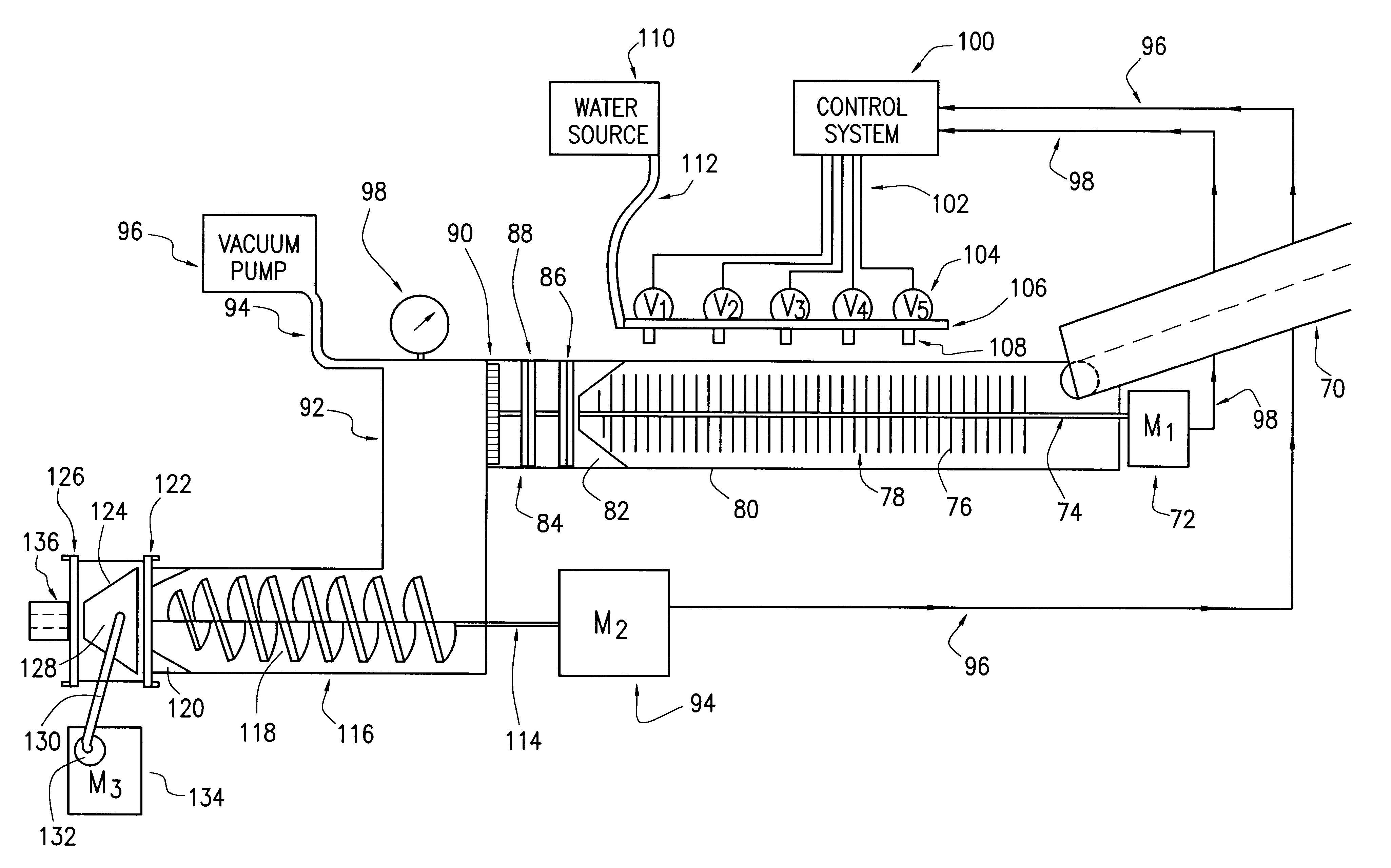
Preferably, the pretreatment chamber includes a first wall with an entry aperture or opening through which the feed mixture enters the pretreatment chamber and a second wall with an exit aperture or opening through which the feed mixture exits the pretreatment chamber. Preferably, the pretreatment section includes a restrictor to increase the density of the feed mixture. Preferably, the pretreatment section further includes at least one stationary plate with ports through which the feed mixture can flow. The stationary plate being disposed between the first and second walls of the pretreatment chamber. Preferably, the pretreatment section includes at least two stationary plates positioned between the first and second walls of the pretreatment chamber, each plate having ports through which the feed mixture flows, the ports preferably being offset to one another, the stationary plates being separated by a distance of from about 2 to 6 inches. Preferably, at least one of the plates is adjustable such that the relative position of the ports in each plate can be changed (e.g., by being rotated) or the distance between the stationary plates can be adjusted. Preferably, the effective flow area provided by the pretreatment section reduces or controls the flow of the feed mixture in an amount sufficient to prevent an undesirable volume, and preferably a substantial volume, of air present in the feed mixture from entering the vacuum zone. Preferably, the flow area is sufficient to prevent air from entering in an amount that would be sufficient to raise the pressure of the vacuum zone.
In a specific embodiment, the step of restricting the flow rate of the feed mixture in the pretreatment zone includes passing the feed mixture through at least two sets of apertures to reduce the flow rate of the feed mixture entering the vacuum zone. These sets of apertures can be separate groups of apertures formed in separate structures where at least two sets or groups of apertures are in different planes relative to the direction of movement of the mixture.
More than one color can be added to the feed mixture at the same time in accordance with another specific embodiment of the invention, and the colors can be variegated, so as to form an uneven striped appearance. It is contemplated that certain color pigments, and certain combinations of color pigments, will provide the
brick with the desired "
brick-like" appearance. For example, in the proper quantities,
iron oxide can provide the extruded article with a red
brick appearance. To lighten or provide a "rough" natural appearance, the feed mixture can be variegated, by adding
titanium oxide in addition to
iron oxide. Other pigments can also be added, such as cupric
oxide.
The blender, dispenser and scale
system can have tanks, which should be constructed of stainless steel to
restrict contamination of the
colored pigments. Prepiped electropneumatic controls can be included. A scale
system can be included, having a compression
cell platform scale with digital readout. Four-color pods and screw feeders constructed of mild steel, with enamel
coating inside can be used, the pods having ball-type vibrators for smoother flow. The pods can be situated on an elevated platform and fork
truck handled for refill operation. Butterfly valves provide for closure of color pod while refilling. Screw conveyors with hydraulic drives can be used to carry the color from the pod to the blender.
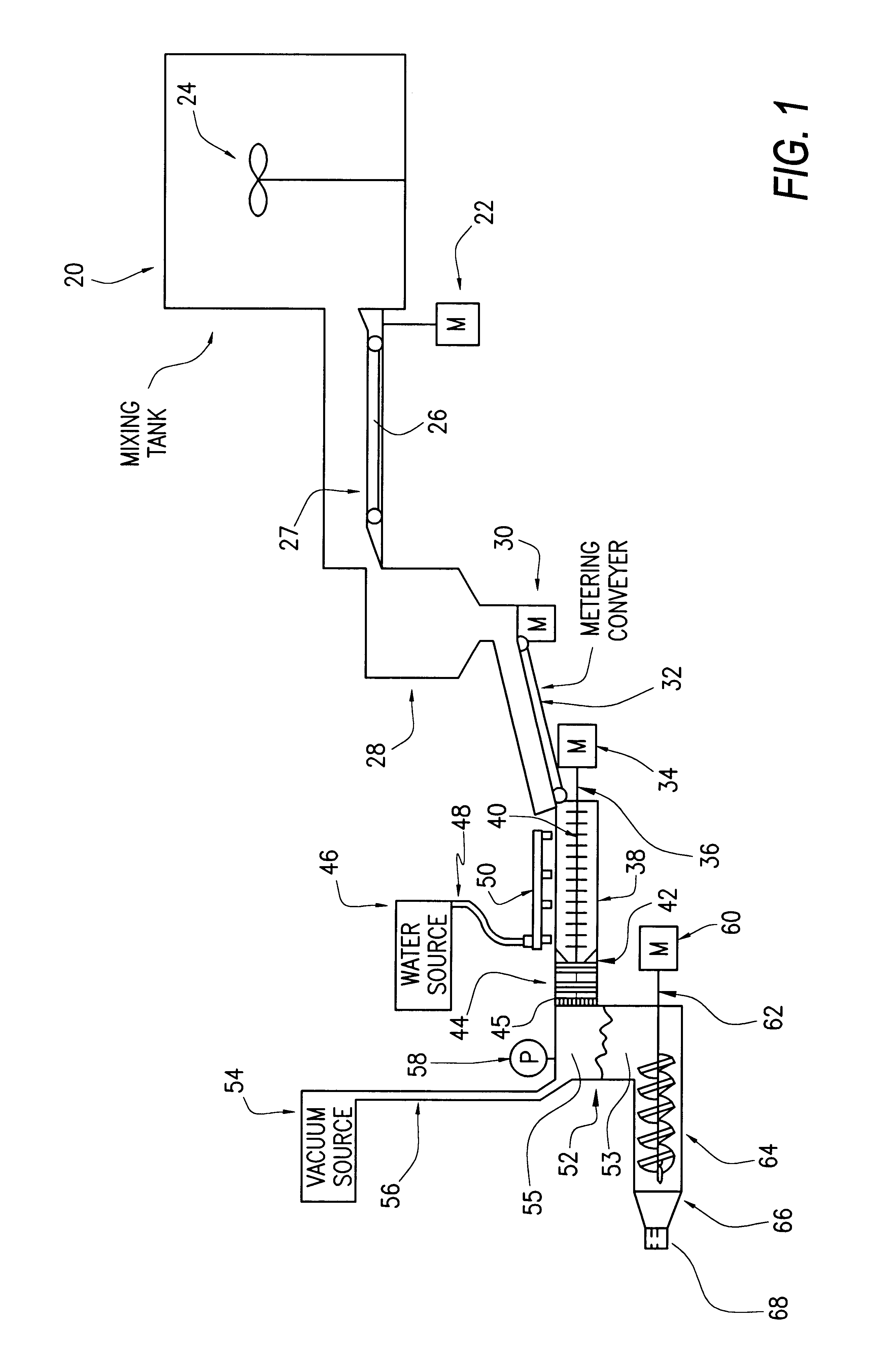
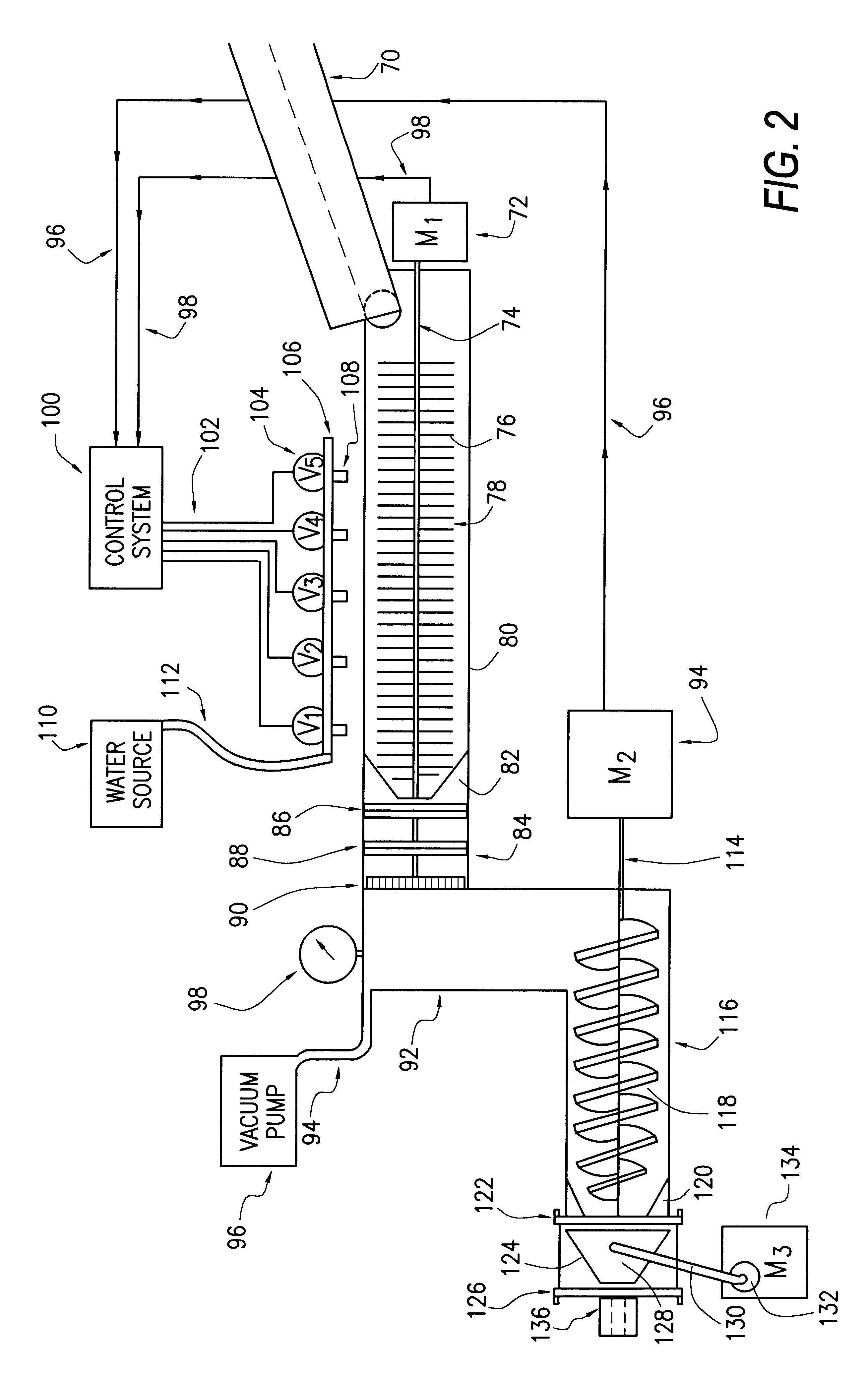
The
extrusion device can be an EEI Premier concrete extruder, which includes a 150 HP main drive. The mixing device can be a 50 HP pug mill, also available from EEI Premier. Both devices can have variable frequency drives. As discussed above, the pug mixer is where the final water addition and mixing is done. While the water is being added, the mix is continually conveyed forward to the
vacuum chamber. The pug mixing blades should be adjustable to control the mix flow. Replaceable wear liners should line the inside of the pug mill chamber. The mixer can be covered with individual
doors that incorporate safety switches that automatically stop the extruder when opened. The
vacuum chamber should be capable of maintaining a 29" of vacuum with a remotely placed
water cooled vacuum system. A 16" main
extrusion auger can be used, with replaceable
auger flights and wear lining on extruder
barrel. A Frecon Series 200
moisture control system can be used, modified in accordance with this invention. An EEI Premier
extrusion die is preferably used, made in accordance with this invention, having vibrating pressure head mounts between the extruder and the stationary die. The pressure head reduces the friction associated with
high pressure extrusion. In accordance with the selective vibration feature of this invention, by oscillating or vibrating the pressure head at varying frequencies, the amount of horse power to extrude is reduced.
Moisture content can also be reduced, forming a stronger product and a stiffer extrusion column. The stationary die is located downstream of the vibrating pressure head. The replaceable stationary die provides the final extruded shape, and is manufactured from high wearing steel with replaceable components. Each die is fitted with a bridge assemblies to form internal voids in the extruded product when required. The die vibration system includes a stationary frame upon which the motor, bearing housings, belts, sheaves, and rotating eccentric shaft are mounted. The eccentric shaft is connected to the pressure head by linkages which create a rocking motion. The
electric motor speed can be controlled so that each extruded article or product may have the optimum oscillating motion to provide strength, production speed and
mix design flexibility.

