
Optical device, a fabricating method thereof, a driving method thereof and a camera system

Inactive Publication Date: 2002-01-08
SONY CORP
View PDF1 Cites 23 Cited by
  • Summary
  • Abstract
  • Description
  • Claims
  • Application Information

AI Technical Summary

Benefits of technology

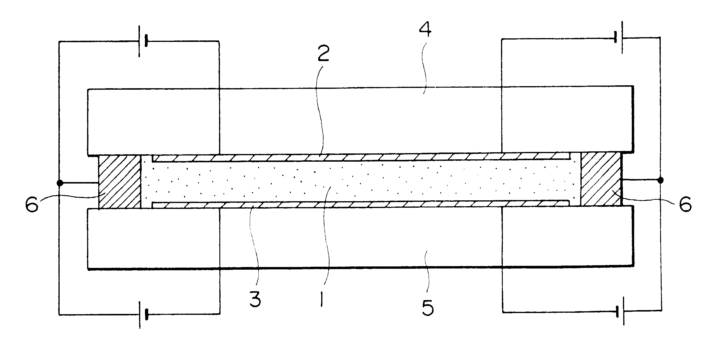
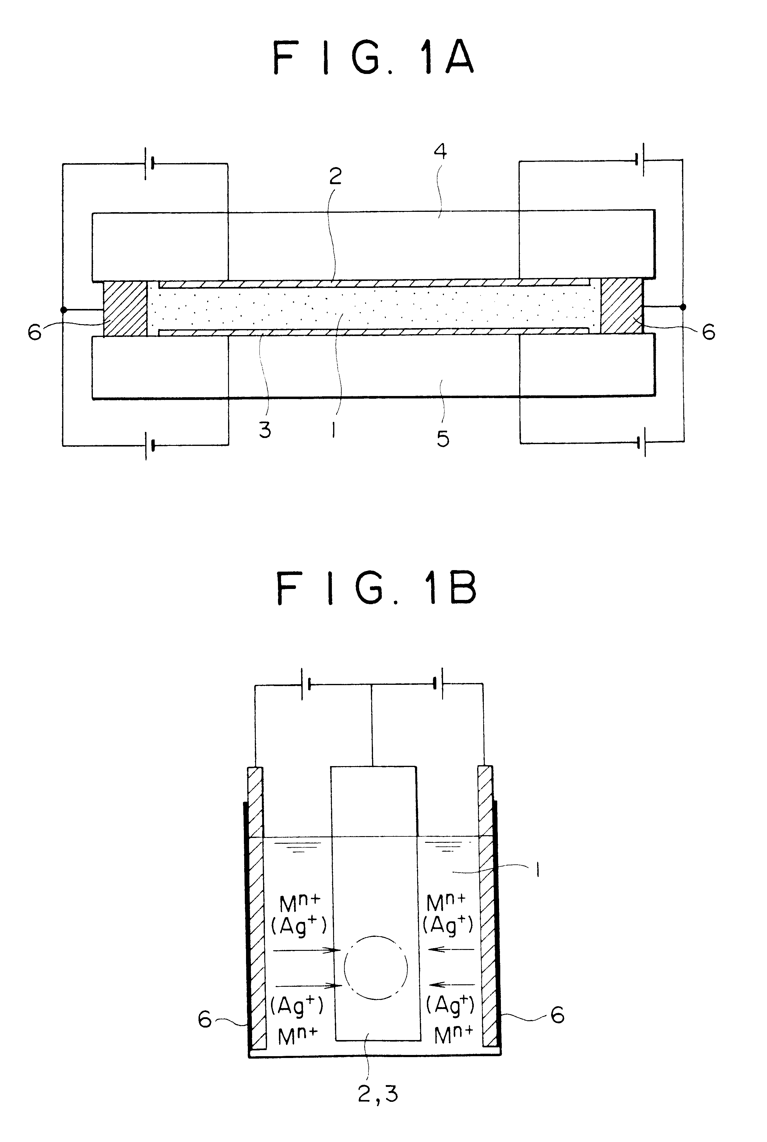
In view of the above, it is an object of the present invention to provide an optical device free from the defoliation as described above, enabling stable driving by stabilizing the potential of the counter electrode and, at the same time, capable of attaining low electric power consumption and improved life of the device, by using a specified material different from the existent material for the counter electrode of an electrochemical light control device utilizing deposition / dissolution reaction of a metal, as well as a method of fabricating the device.
Since the optical device according to the present invention can control the amount of light by the application of the electric field as described previously, it requires no mechanism for driving the diaphragm and is different basically from the existent mechanical light amount control mechanism, so that the system can be reduced in the size, substantially, to the effective range of the optical width. Accordingly, it is possible to reduce the size of the CCD camera. Furthermore, since the amount of light can be stably controlled appropriately depending on the level of the voltage applied to the patterned electrodes, diffraction phenomenon in the prior art can be prevented and a sufficient amount of light can be entered into an image sensing device to eliminate image blurring. Since the optical device according to the present invention can be driven stably, stable light amount control is possible if the light control cell of the optical device according to the present invention is attached on the identical optical path for the light amount control (light amount restriction), stable optical amount control is possible.

Problems solved by technology

However, ECDs using the viologen molecule derivatives involve a problem that response speed or degree of shielding is insufficient.
In addition, as a light amount control device, it is necessary that the light transmissivity can be controlled in a visible light vision (wavelength at 400 to 700 nm), and no sufficient characteristics can be obtained with the ECD material as described above.
However, when a pure metal plate is used for the counter electrode, since the oxidation / reduction reaction is not uniform as the life of the device is increased, inactivated metal particles deposited on the counter electrode suspend in the electrolyte to contaminate the inside of the device and lower the transparency upon driving of the device, which may lead to a problem of lowering the transmissivity to the visible light or causing short-circuit between the electrodes.
When such metal A is increased in the electrolyte, it lowers the transparency of the device upon color extinction of the working electrode and such metal particles also cause short-circuit between the electrodes to cause a significant problem that has to be dissolved when the metal plate is used as the counter electrode of the device.
Further, if the material allows relatively smooth charge transfer to the electrolyte, it causes deposition of silver or a silver-containing compound on the current collector or side reaction such as decomposition of electrolyte ingredients.
Since such great polarization resistance not only causes large electric power consumption but also promotes the side reaction, it results in a problem of shortening the life of the device.
This gives undesired effects on the light transmissivity or reflectivity in the optical device to cause lowering of characteristics of the optical device and deteriorate the optical device.

Method used


Image

  • Optical device, a fabricating method thereof, a driving method thereof and a camera system
  • Optical device, a fabricating method thereof, a driving method thereof and a camera system
  • Optical device, a fabricating method thereof, a driving method thereof and a camera system

Examples


first example

In this example, the cell structure of an electrochemical light control device (optical filter) has similar constituent parts to an existent structure explained with reference to FIG. 3 and FIG. 4. As shown in an enlarged view in FIG. 6, it is a significant feature to dispose a counter electrode and a reference electrode according to the present invention (FIG. 7 shows a schematic cross section for the entire cell structure).

As shown in FIG. 6, a counter electrode 17b and a reference electrode 16b are formed as a laminate structure of an underlying layer (a second layer) 19 comprising ITO and a first layer 18 comprising platinum on a glass substrate 12. The counter electrode 17b and the reference electrode 16b are surrounded at the circumferential edge thereof with black resist 30 in intimate contact in which the surface of the counter electrode or the reference electrode is at the position nearer to the substrate than the black resist surface (lower position). The same constitution...

second example

A beaker cell test was conducted and the polarization characteristic of the counter electrode was examined in the same manner as for Example 1 except for applying silver as the third layer 38 on the first layer (platinum layer) of the counter electrodes (17a, 17b) of the substrate obtained in Example 1 by an electrolytic plating method (refer to FIG. 21). The result of a beaker test cell is shown in FIG. 22.

Silver was plated on the platinum surface of the counter electrodes in a solution of the same composition as that in the electrolyte sealed in the cell by supplying a current at a constant current density of 18 mA / cm.sup.2 to platinum in the reduction (basic) direction for 2 min.

In this example, since the silver layer is previously formed on the surface of the counter electrode 17B, dissolution / deposition reaction of silver proceeds smoothly and it can be seen that polarization at the reference electrode relative to the silver plate is reduced extremely also upon polarization to ...

third example

A counter electrode comprising two layers was prepared in the same manner as in Example 1 except for EB vapor deposition of palladium instead of platinum as the first layer for the electrode and then silver was formed as a third layer thereon in the same plating method as in Example 2 (identical with the structure shown in FIG. 21). Further, the cell structure was also identical with that in Example 1. Silver plating on the palladium surface vapor deposited to the substrate was conducted in a solution of the same composition as that of the electrolyte sealed in the cell by supplying a current at a constant current density of 18 mA / cm.sup.2 to palladium in the reduction (basic) direction for 2 min.

At first, for examining the polarization characteristic of the counter electrode, a test was conducted under the same conditions in the same beaker cell as in Example 1. Further, for the cycle evaluation, a test was conducted in the same manner and the results are shown in FIG. 24.

Also in t...


PUM


Abstract

An optical device used for an optical filter or the like capable of controlling a light transmittance or light reflectance in a visible light region, a fabrication method thereof, a driving method thereof and a camera system are provided, including the optical device comprising a working electrode and a counter electrode in which an electrolyte is disposed in contact with both of the electrodes and light is controlled electrochemically by controlling an electric field applied to the electrolyte, and a first layer of the counter electrode present on the side of the electrolyte comprises a metal having a lower ionization tendency than that of a metal deposited at the working electrode, an optical device having a reference electrode having no direct concerns with oxidation / reduction reaction of the working electrode and the counter electrode for measuring the potential for one or both of the electrodes, a method of fabricating an optical device having a counter electrode and a reference electrode comprising a single layer or a laminate structure, comprising forming each of the layers by a gas phase film forming method or the like and forming each of the electrodes as a thin film of a predetermined pattern by etching, a method of driving the optical device by measuring the potential of the working electrode and the counter electrode to the reference electrode and controlling the supply of current as well as a camera system mounting the optical device.

Description

1. Field of the InventionThe present invention concerns an optical device suitable, for example, to display apparatus for conducting display of numericals or characters or X-Y matrix display, as well as an optical filter capable of controlling light transmissivity or light reflectivity in a visible light region (wavelength at 400 to 700 nm), as well as a fabricating method thereof, a driving method thereof and a camera system.2. Description of the Related ArtAn electrochromic display device employed in display apparatus such as digital watches (hereinafter simply referred to as "ECD") is a non-light emission type display device which conducts display by reflection light or transmission light as a light control device by electrochemical operation, so that it has a merit giving less feeling of fatigue even in long time observation, as well as a merit that if requires relatively low driving voltage and less consumption power.For instance, as disclosed in Japanese Published Unexamined P...

Claims


Application Information

Patent Timeline
IPC IPC(8): G02F1/01G02F1/15G02F1/163G02F1/155G02F1/1506
CPCG02F1/1506G02F1/163G02F1/155
Inventor KIHIRA, TORUUDAKA, TORU
Owner SONY CORP
Learn More