Multi-anode device and methods for sputter deposition

a technology of multi-anode devices and sputters, applied in vacuum evaporation coatings, electrolysis components, coatings, etc., can solve the problems of not necessarily providing control of coating thickness, not necessarily addressing controlling the thickness uniformity of reactive coatings, and system typically not producing uniformly thick coatings on multiple articles disposed

Inactive Publication Date: 2002-08-27
SOLA INTERNATIONAL INC
View PDF23 Cites 47 Cited by
  • Summary
  • Abstract
  • Description
  • Claims
  • Application Information

AI Technical Summary

Benefits of technology

Ophthalmic lens elements are frequently coated to achieve special properties. Anti-reflection coatings improve the transmittance of visible light and the cosmetic appearance of the lenses. Reflective and absorptive coatings may be employed in sun lenses to reduce light transmittance to the eye, to protect the eye from UV radiation and / or to impart cosmetic colorations to the lens. Coatings may also provide other beneficial properties such as increased hardness and scratch resistance and anti-static properties.
The Fuzzy Logic Toolkit for LabVIEW may be used as a basis for a customized fuzzy logic editor. This editor allows the operator to easily toggle between the membership functions of the inputs and outputs, as well as edit the rulebases for both outputs. The amount of time required for the operator to precisely tune to the control algorithm is reduced. As the system or product requirements change, the algorithm can be readjusted to account for these changes.

Problems solved by technology

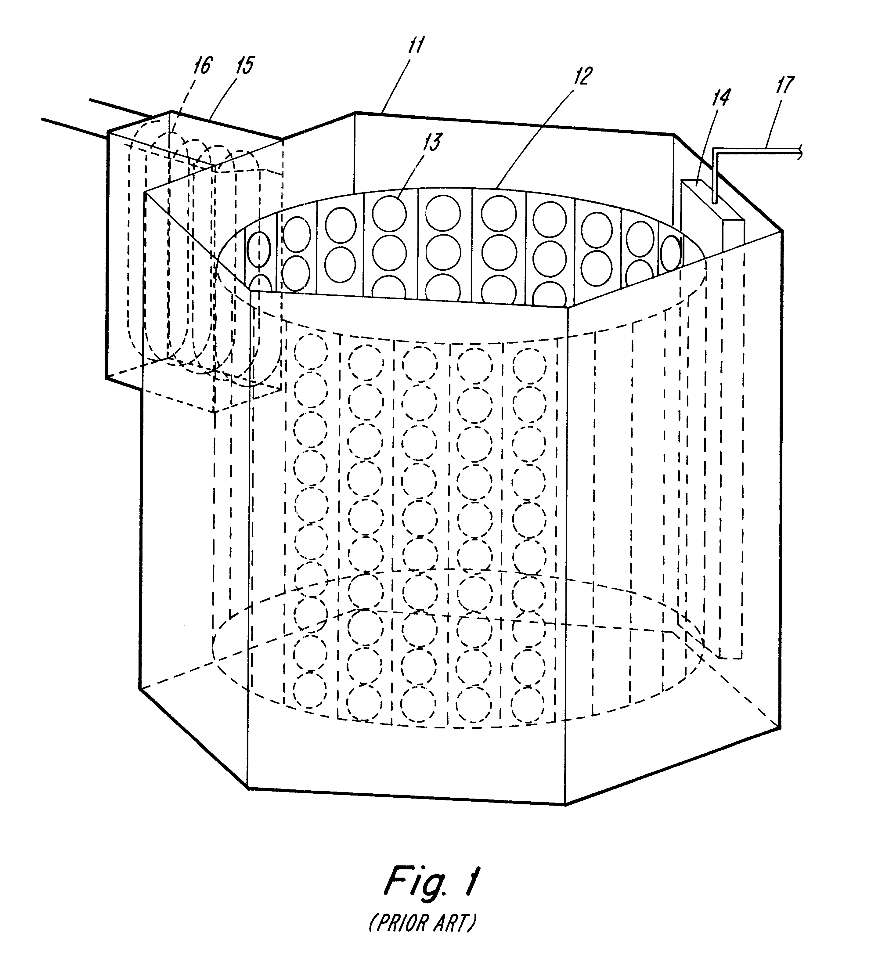
However, Applicants have observed that such systems typically do not produce uniformly thick coatings on multiple articles disposed in a given column of the drum 12 due to the variation in sputter rate along the length of the sputter source.
While this approach provides control of the electrical resistance of the coating, it does not necessarily provide control of the coating thickness, a quantity of importance for optical coatings.
The disclosure in the '225 patent, however, does not address controlling the thickness uniformity of reactive coatings deposited on large numbers of individual lens elements using an elongated magnetron sputter source in a drum vacuum coating system.
However, Applicants have observed that such systems typically suffer from the inability to produce coatings of uniform thickness on multiple articles disposed in various locations on the drum due to variations in the sputter rate along the length of the sputter source.
These causes includes: historical effects on the target (such as oxide coverage and oxygen implantation), target cleaning, tooling cleaning, chamber cleaning, length of time the chamber is opened for loading, unloading or servicing and consequent coverage of chamber and tooling with absorbed layers of water vapor, thickness of deposited materials on tooling and chamber, type of plastic constituting the lens substrates and their degree of water uptake, gas leaks, improper calibration of partial pressure gauges and / or other means of measuring partial pressures such as Optical Gas Controllers.
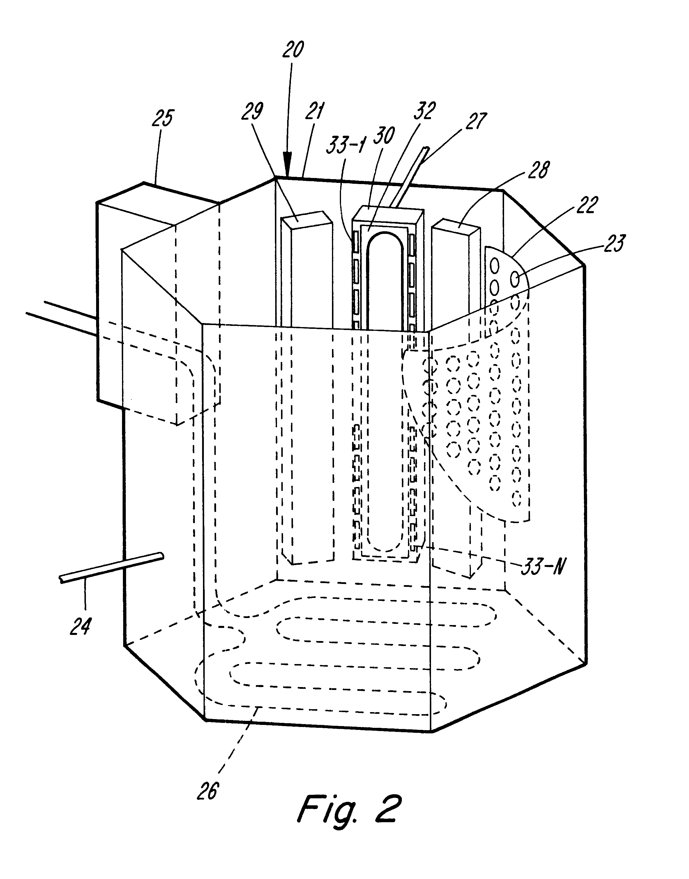
However this body rapidly becomes coated with insulating dielectric materials in reactive sputter coating so that the surface exposed to the plasma may float at a potential above ground potential and therefore lead to the well known wandering anode problem which contributes to non-uniform sputter deposition.
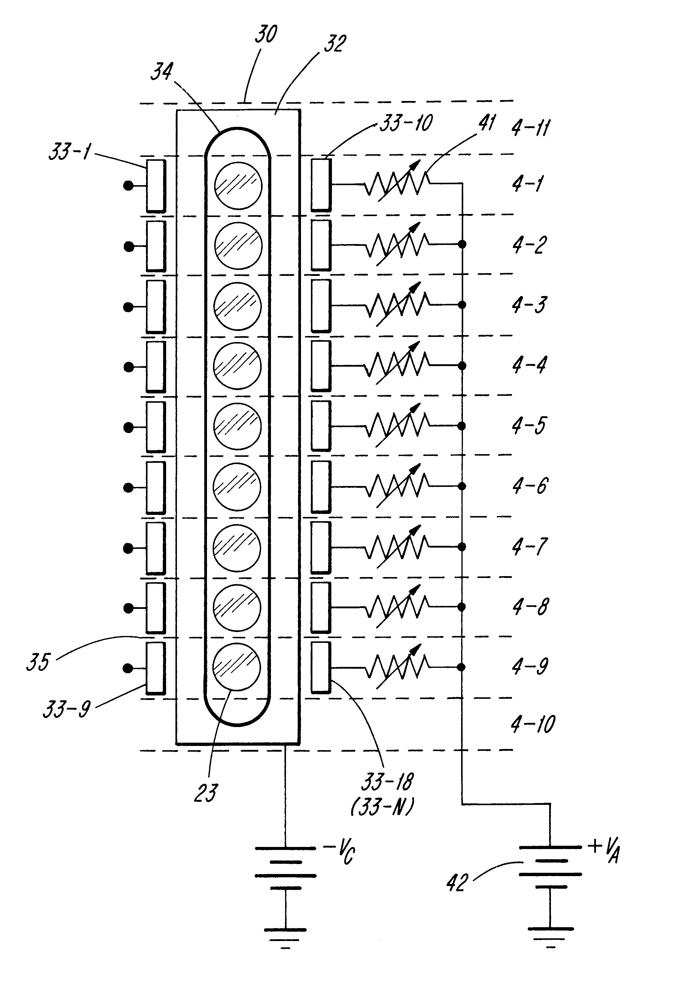
This scheme will only work if the anodes 33-1 through 33-18 are effectively uncoated by dielectric whilst the chamber in the vicinity of the sputter magnetrons is substantially coated with electrically insulating dielectrics and therefore does not provide a good ground potential.
Sharp points on the ends of the wire lead to high electric field strengths which lead to breakdown of any oxides deposited on them.
The purpose of this is to discharge the islands of metal oxide on the target which would otherwise build up charge to the point where they would lead to an electrical breakdown of the oxide film and consequently cause a localized arc which has various deleterious effects.
In a conventional system there is a difficulty with this technique in that, as soon as the sputter power supply begins to reverse its polarity, the sputter plasma dies and there are few electrons left to neutralize the positive charge on the islands of oxide.
Furthermore, the few electrons which are left to do this duty are bottled up in the magnetic field of the sputter magnetron and are not at liberty to neutralize charge on the islands of oxide outside the magnetic bottle where they are most needed.
However, in this case the impact on the microwave plasma will be of longer duration and the drain of electrons from it may be evidenced by a longer period in which the microwave power source is mismatched to the plasma.
The microwave power reflected from the plasma may have deleterious effects on said microwave power source and these need to be monitored and guarded against if necessary.
The interrelationships and dependencies of the variables are complicated.

Method used


Image

  • Multi-anode device and methods for sputter deposition
  • Multi-anode device and methods for sputter deposition
  • Multi-anode device and methods for sputter deposition

Examples


Embodiment Construction

The following is an example of a fuzzy logic control process calculation. In the example, we shall assume that the instantaneous operating point has drifted to a Cathode Voltage=370 Volts (Line A of FIG. 10(a)) and a Total Pressure of 8.82 mBar (line B of FIG. 10(b)). From the graphs of FIG. 10(a), one may obtain a Voltage Membership 0.75 "LO" and 0.25 "OK". From the Pressure Membership Functions of FIG. 10(b) one may obtain the pressure membership values of 0.30 "OK and 0.70"HI. (Note that these membership functions happen to add up to 1.00 in each case but they do not in general need to). These membership function values are shown in the top left hand box of FIG. 11 which will be used to track the calculation of the output for oxygen flow (i.e. percent valve opening of a piezoelectric valve).

Next, the membership of the output sets (DECRease, HOLD, INCRease) for oxygen is calculated. Two Rules are used to do this. The appropriate First Rule applied to the Pressure and Voltage membe...


PUM

PropertyMeasurementUnit
lengthaaaaaaaaaa
lengthaaaaaaaaaa
lengthaaaaaaaaaa

Abstract

A method and apparatus for vacuum coating plural articles employs a drum work holder configuration and a sputter source with a plurality of individually controlled anodes for effectively providing uniform coatings on articles disposed at different locations on the drum work holder. A small number of measured process parameters are used to control a small number of process variable to improve coating uniformity from batch to batch.

Description

The present invention relates to methods and apparatus for sputter coating articles, and especially, for reactive sputter coating of plastic ophthalmic lens elements using a sputter source with multiple anodes. As used herein, lens elements include, according to context, edged lenses, semi-finished lenses and lens blanks. Also included are wafers for forming laminate lenses or wafer blanks therefor. Ophthalmic uses of the lens elements include uses in eyeglasses, goggles and sunglasses.BACKGROUND AND OBJECTS OF THE INVENTIONMany ophthalmic lenses produced today are made from a single plastic body or laminated plastic wafers. The plastic material may include thermoplastic material such as polycarbonate or thermoset material such as diallyl glycol carbonate types, e.g. CR-39 (PPG Industries). The material may also be a cross linkable polymeric casting composition such as described in U.S. Pat. No. 5,502,139 to Toh et al. and assigned to applicant.Ophthalmic lens elements are frequentl...

Claims


Application Information

Patent Timeline
Patent Type & Authority Patents(United States)
IPC IPC(8): C23C14/54C23C14/00C23C14/35C23C14/50H01J37/32H01J37/34
CPCC23C14/0078C23C14/354C23C14/505C23C14/542H01J37/3405H01J37/3438
Inventor BURTON, CLIVE H.PRATT, RODNEYSAMSON, FRANK
Owner SOLA INTERNATIONAL INC
Why Eureka
Try Eureka