
Apparatus and method for optimized self-synchronizing serializer/deserializer/framer

a serializer and framer technology, applied in the field of computer systems, can solve the problems of affecting the design time of the integrated circuit, the inability to transmit data in parallel format over significant distances, and the inability to transmit high-speed serial data signals on the receiving end, so as to increase the design time of new products, the effect of reducing the cost of production and high data transmission speed

Inactive Publication Date: 2002-10-01
MEDIATEK INC
View PDF9 Cites 96 Cited by
  • Summary
  • Abstract
  • Description
  • Claims
  • Application Information

AI Technical Summary

Benefits of technology

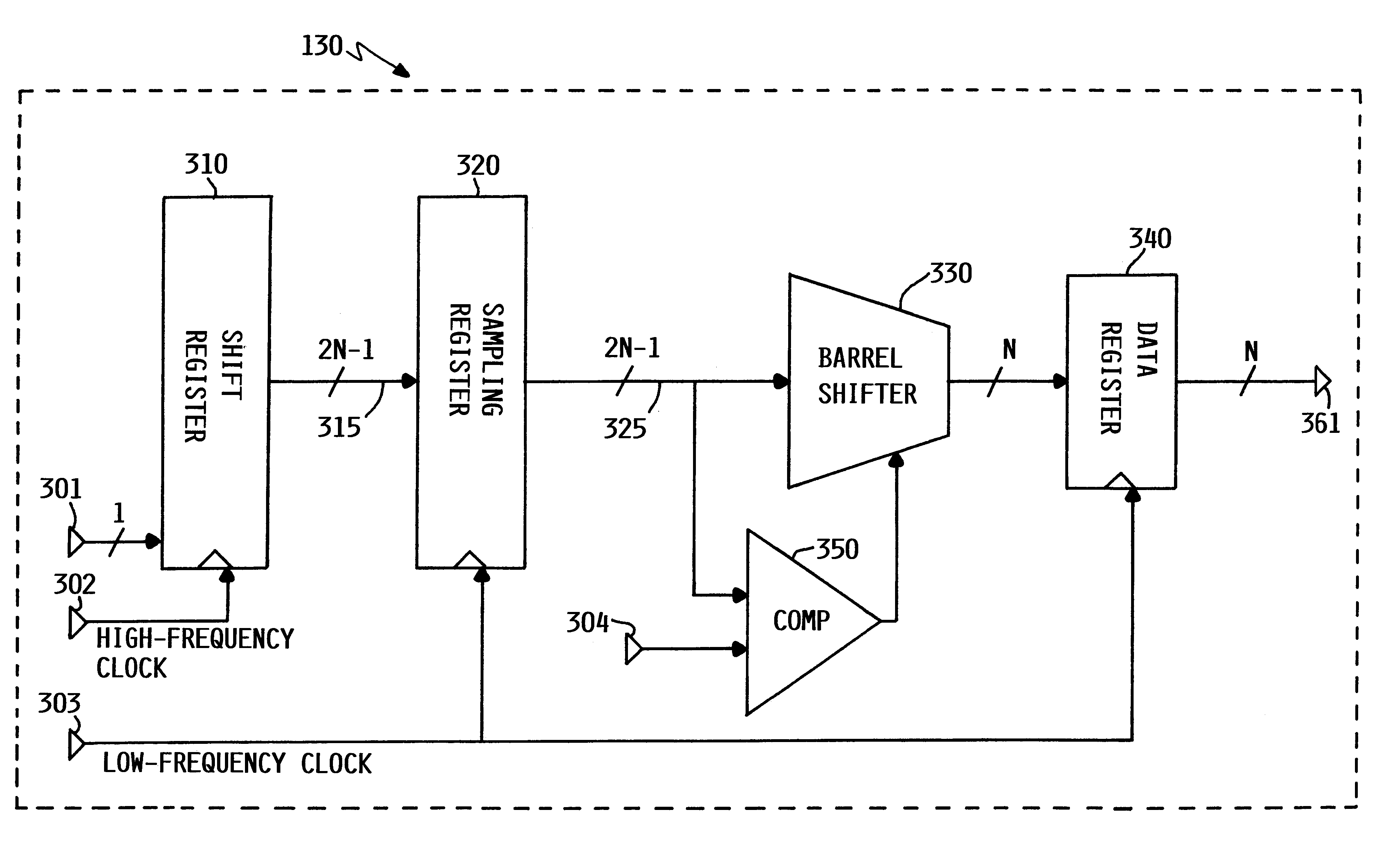
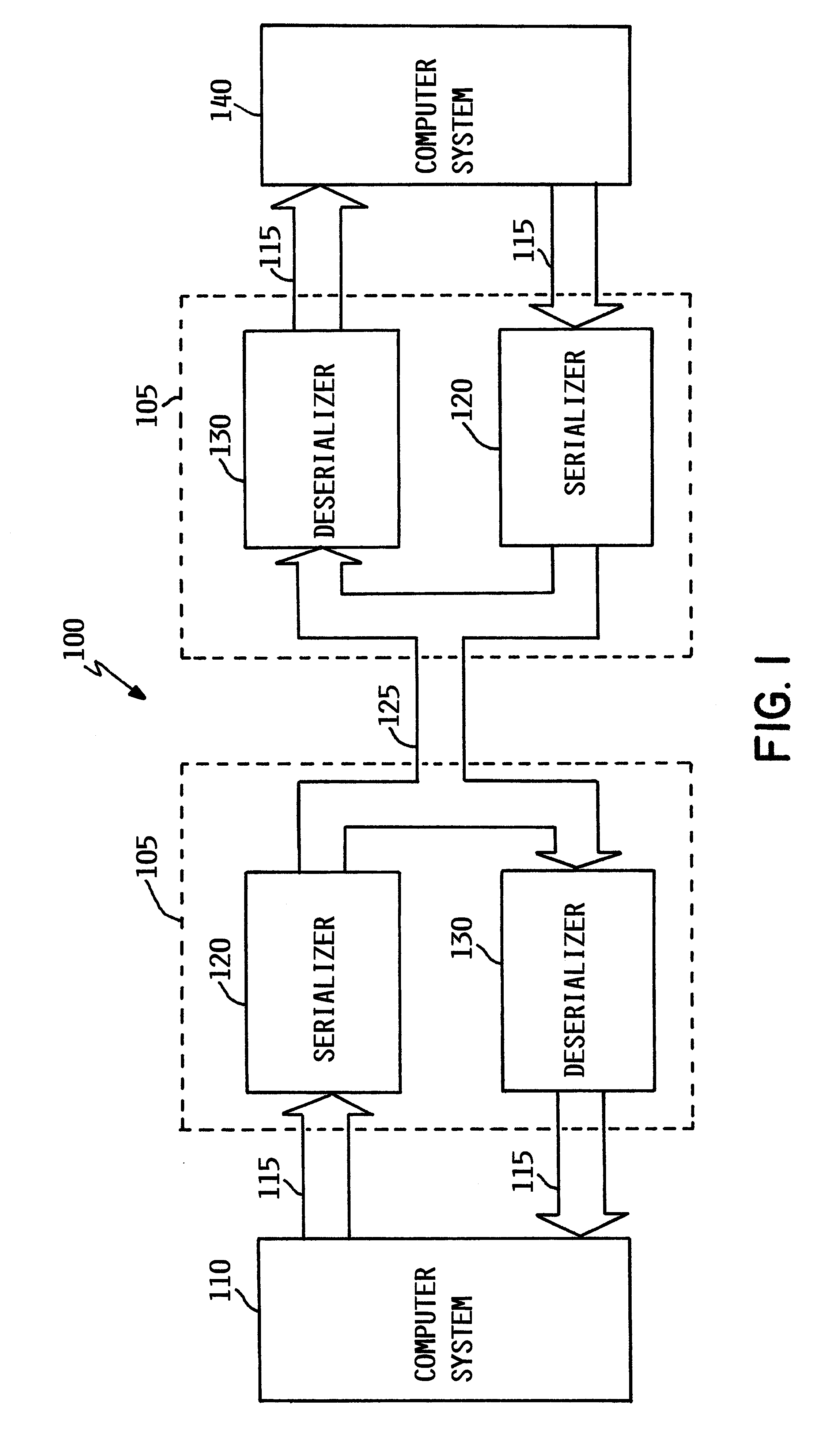
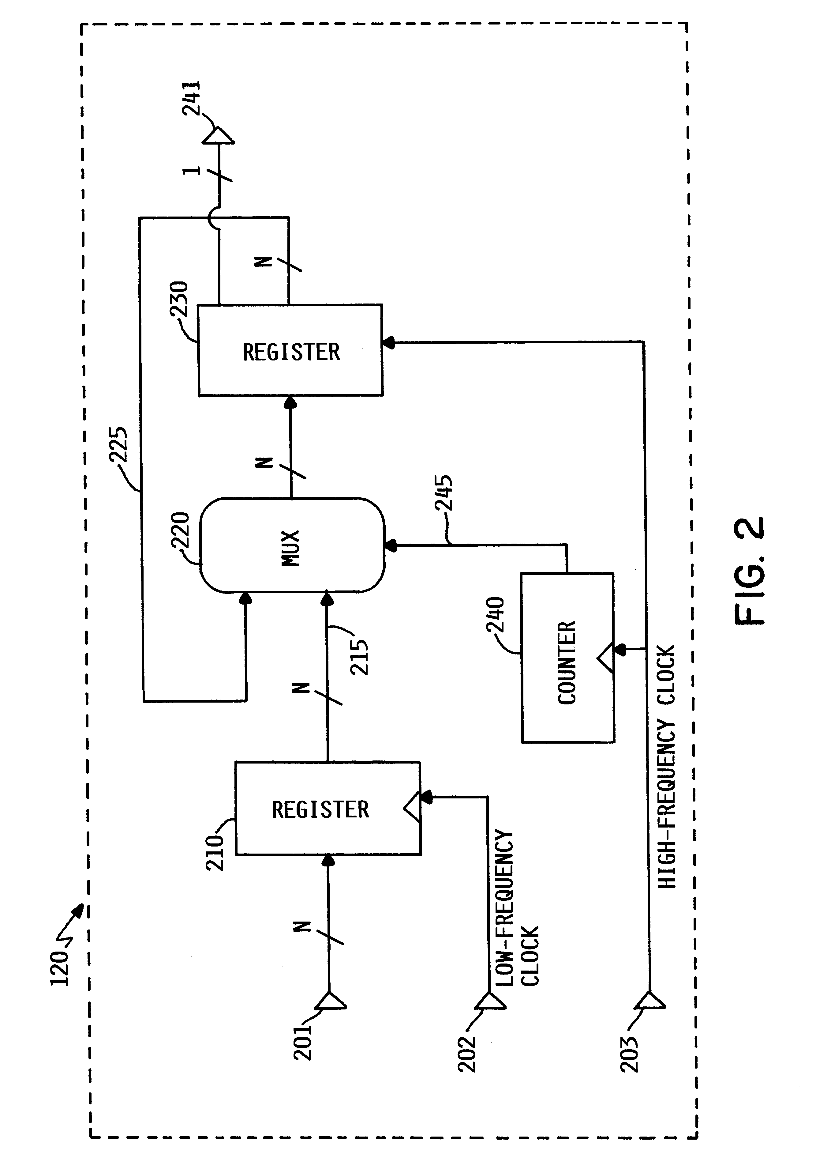
According to the preferred embodiments of the present invention, an apparatus and method for improving the communication capabilities of computer systems is disclosed. The serializer and deserializer of the present invention each utilize a pair of related clock signals to allow the operation of a self-synchronizing device. No external synchronization signal is necessary for the operation of the serializer or deserializer. The most preferred embodiments of the present invention use a series of data buffers and data registers to process an incoming high speed data signal. By using the buffers and registers, the incoming signal can be reformatted and manipulated at a much lower frequency than the original transmission frequency. The deserializer of the present invention also samples a greater portion of the incoming data signal than usual to further increase reliability by reducing circuit complexity and timing issues. These various features of the invention provide for a more stable and reliable communication link and will also provide a less expensive solution for serialization / deserialization.
As one example, the SONET standard at the 155 Mbit transmission rate uses a six byte framing sequence to initially identify or delineate a 2430 byte frame of data. This means that there is a series of information bytes defined by SONET that are always positioned to be the first six bytes of every frame transmitted. These six "framing bytes" are called A1, A1, A1, A2, A2, and A2. The value of each of the six framing bytes, respectively, is always 0xF6, 0xF6, 0xF6, 0x28, 0x28, and 0x28. These six framing bytes effectively signify and mark the start of each frame. Since many other transmission functions are also performed with respect to a given frame of data, (e.g., parity calculations across the frame, frame synchronous data scrambling, location of overhead information within the frame header, etc.) these six fixed-position framing bytes provide the reference markers which allows the rest of the information contained in the frame to be properly recovered without the use of additional markers to identify each different portion of the data in the frame. By locating the framing bytes and using a calculated offset, each and every byte of information within the frame can be quickly and accurately identified according to the promulgated standard. This allows the receiving station to efficiently and effectively reformat the serial data stream into a parallel data stream upon receipt. The other standard protocols listed above also employ some roughly analogous series of framing bytes or a framing sequence identifier to mark the beginning of each frame of data.
Similar to the SONET standard, the Fibre-Channel protocol uses a single 10-bit framing sequence called K28,5 which uses a unique framing pattern with the value of 0b0011111010 or 0b1100000101. As with the SONET standard, the Fibre-Channel protocol uses these 10 bits to identify the beginning of each frame, thereby permitting data manipulation to take place in a systematic way for all data transmitted using this protocol.
Although the use of a unique framing pattern to mark the beginning of a frame is widespread, when existing SERDES units perform the required processing and framing functions for high-speed serial data streams, it is often difficult to control design factors such as timing, clock loading, and signal noise. Since every data signal takes a certain amount of time to be processed through a SERDES, timing limitations and synchronization requirements can become controlling factors at very high data transmission speeds. These high-speed communication-related problems can negatively impact design time, integrated circuit clock loading, and signal noise. This, in turn, can increase new product design time, introduce unnecessary complexity into the system, and increase overall signal transmission costs. As physical transmission media technology improves, theoretical transmissions speeds will also improve. However, given the practical limitations of existing SERDES equipment, it may not be possible to translate theoretical limits into actual transmission speed gains.

Problems solved by technology

While the parallel transmission of data is useful for the short data paths that exist within most computer systems, transmitting data in a parallel format over significant distances is not practical due to the increased cost and difficulty of implementing parallel data paths over a long distance.
While the general process for transmission of digital data via high-speed communication links is well known, there are several significant limitations associated with the existing methods.
One of the most significant problem associated with transmitting high speed serial data signals occurs on the receiving end.
As the frequency of the incoming data signal increases, this becomes increasingly difficult to accomplish because most presently used receiving equipment simply cannot reliably process the data and transform it beyond certain frequency thresholds.
While it is desirable and theoretically possible to further increase the speed of transmission for serial data signals beyond the currently employed levels, existing deserialization equipment cannot reliably extract the information and reformat the data signal into parallel form at higher frequencies.
The theoretical limits of high-speed data communications have not yet been reached due to the physical and logical constraints in the commonly used components of presently known devices.
The intricate timing and coordination requirements necessary to process increased frequency high-speed data signals is beyond most currently available solutions.
In addition, the design and use of next-generation high-speed components that can efficiently and effectively process high-speed serialized data signals is very expensive.
This limits any possible solutions using these high-speed components to a fairly narrow range of applications where cost is not a significant factor.
Without providing improved equipment and techniques for high-speed computer communications, information transfers over computer networks will continue to be less than optimal.
The practical constraints of the present equipment and methods will, therefore, remain a limiting factor and will continue to slow the growth and beneficial use of computer transmitted data, particularly at the more desirable high speeds.

Method used


Image

  • Apparatus and method for optimized self-synchronizing serializer/deserializer/framer
  • Apparatus and method for optimized self-synchronizing serializer/deserializer/framer
  • Apparatus and method for optimized self-synchronizing serializer/deserializer/framer

Examples


Embodiment Construction

The present invention includes a serializer that receives parallel data input from a computer and serializes the data for transmission over a high-speed serial communication link. On the receiving end, the present invention provides a deserializer that can quickly and efficiently transform the serial data back into parallel form for use within the computer system on the receiving end. By utilizing two related clock signals, one clock signal being an integer multiple of the other, a self-synchronizing serializer / deserializer can be created. In addition, by using data buffers and data registers to increase the size of the data sample on the receiving end, the comparisons necessary to construct a parallel signal from a serial transmission can occur at a much lower frequency than the frequency of the original serial transmission. This feature reduces complexity and increases reliability. In the most preferred embodiment, the invention is provided as a integrated solution manufactured on...


PUM


Abstract

An apparatus and method for improving the communication capabilities of computer systems is disclosed. The most preferred embodiments of the present invention use a series of data buffers and data registers to process an incoming high speed data signal. By using the buffers and registers, the incoming signal can be reformatted and manipulated at a much lower frequency than the original transmission frequency. The deserializer of the present invention also samples a greater portion of the incoming data signal than usual to further increase reliability. These various features of the invention provide for a more stable and reliable communication link and will also provide a less expensive solution for serialization / deserialization. The present invention includes a serializer that receives parallel data input from a computer and serializes the data for transmission over a high-speed serial communication link. On the receiving end, the present invention provides a deserializer that can quickly and efficiently transform the serial data back into parallel form for use within the computer system on the receiving end. By utilizing two related clock signals, one clock signal being an integer multiple of the other, a self-synchronizing serializer / deserializer can be created. In addition, by increasing the size of the data sample on the receiving end, the comparisons necessary to retrieve a parallel signal from a serial transmission can occur at a much lower frequency than the frequency of the serial transmission. In the most preferred embodiment, the invention is provided as a integrated solution manufactured on a Peripheral Component Interconnect (PCI) card, thereby allowing the present invention to be easy installed into existing computer systems.

Description

1. Technical FieldThis invention generally relates to computer systems and more specifically relates to transmitting digital data from one location to another.2. Background ArtThe development of the EDVAC computer system of 1948 is often cited as the beginning of the computer era. Since that time, computer systems have evolved into extremely sophisticated devices, and computer systems may be found in many different settings. Computer systems typically include a combination of hardware (e.g., semiconductors, circuit boards, etc.) and software (e.g., computer programs). As advances in semiconductor processing and computer architecture push the performance of the computer hardware higher, more sophisticated computer software has evolved to take advantage of the higher performance of the hardware, resulting in computer systems today that are much more powerful than just a few years ago.Computer systems typically include operating system software that controls the basic function of the c...

Claims


Application Information

Patent Timeline
IPC IPC(8): H03M9/00H04L25/40H04L25/45C12N7/01
CPCH03M9/00H04L25/45
Inventor NORDMAN, JOHN EMERY
Owner MEDIATEK INC
Learn More