
Adhesive transparent resin and a composite including the same

a transparent resin and composite technology, applied in the direction of synthetic resin layered products, film/foil adhesives, sensing by electromagnetic radiation, etc., can solve the problems of increased danger, more serious accidents, and increased danger to the human body

Inactive Publication Date: 2002-10-15
ASAHI KOGAKU KOGYO KK
View PDF26 Cites 11 Cited by
  • Summary
  • Abstract
  • Description
  • Claims
  • Application Information

AI Technical Summary

Benefits of technology

The solution provides coatings with enhanced adhesion, durability, and UV resistance, enabling safer and more efficient use in electronic materials, glass substrates, and UV-cutting applications, while reducing packaging volume and improving handling and storage conditions.

Problems solved by technology

For example, when the reflection-free glass is used as a construction material, particularly those for high-rise buildings, damage of the glass due to earthquakes and other causes will result in a very dangerous situation to the human body, because when the reflection-free grass is crushed, fragments fall onto the surface of the ground.
Further, for indoor use, for example, when the reflection-free glass is used as a display of electric equipment, furniture and the like, there is a possibility that the glass crushed due to an unexpected accident causes injury.
Furthermore, when the reflection-free glass is used as a part of the large-sized machine equipments in factories, there is a possibility that tiny particles of glass may further induce a more serious accident, namely, the degree of danger would be further increased.
However, the use is inevitably limited to a specific range, because the use of adhesives can result in drawbacks such as separation from a surface of the adherend, if the adhesive and the adhesive-applied products are exposed to conditions of high temperature and high humidity.
However, the above-mentioned means are insufficient to satisfy the requirements to an adhesion property under a high temperature and high humidity conditions.
Particularly, the means do not provide a satisfactory suggestion concerning the adhesion property between a glass substrate and an optical film.
However, use of wooden frames causes a remarkable increase of bulk (or volume) of the packaged glass, i.e., two or more times of the volume of the plate glass itself to be packed, and contrary to such an increase of bulk, the resulting shock resistance is not always satisfactory to the requirements.
Further, foamed plastic sheets, rugged sheets or other sheets have been utilized as packaging materials to transport or store glass articles or potteries, however, these sheets also can not always provide a sufficient shock resistance.
When sunlight is irradiated onto various architectural structures or a glass surface thereof, there may be a loss of comfort to the occupants as a result of an increase of the temperature of the interior space of the structures.
Further, there is a risk of the human health being adversely affected due to ultraviolet rays of the irradiated sunlight.
Furthermore, because of an increase of the temperature of the articles disposed in the inside of a structure, the articles may cause a change in their color or properties.
However, these methods based on the addition of the dye or absorbing agent can merely retain their effects concerning the fastness only for about one to two years, because the added dye or absorbing agent per se is deteriorated in properties.
Further, for the prior art UV-cut films, it is difficult for laymen not skilled in the art to correctly laminate the film on a glass surface as the adherend without causing creases or rumples, and once it has been laminated, the film can not be removed from the glass surface.
The CRTs, however, suffer from problems such as adhesion of dust, dirt on the film, and difficulties in viewing the CRT due to light emitted from fluorescent lamps or a window (reflective projection).
Further, with the increase of the workload of the VDT as a result of widespread use of personal computers and word processors, the health-hazard due to electromagnetic waves, ultraviolet rays and electrostatic charges generated or emitted from the CRT devices, as well as safety measures, have become a serious issue.
In order to prevent the reflective projection of fluorescent lamps and light reflection from windows to the surface of the CRTs, which is a cause of visual difficulties, there has been suggested to use an anti-reflective filter, however, the fastening of such an anti-reflective filter to a CRT surface is troublesome.
However, the anti-static effect has not been satisfactory and therefore the adhesion of dust, dirt and the like can easily fire the eye shortly after the application of the anti-static layer.
The ultraviolet rays can cause a fatigue of the eyes.
Furthermore, recently, the importance of the effect on human health due to the electromagnetic waves is being made apparent, however, it is true to say that substantially all of hard coated films and CRT filters in the prior art do not take measures to protect the human eyes from electromagnetic waves and ultraviolet rays emitted from the CRTs.
However, plastic lenses having both an applied hard coated layer and an anti-reflective layer suffer from the drawback of a remarkably reduced shock resistance in comparison with the plastic lenses without applied layers or the plastic lenses with the hard coated layer only.
However, since the urethane resin is formed by the thermal curing process, several hours for curing time may need until the primer layer is formed.
Moreover, for primers of the prior art, it was not possible to adjust interference fringes generated between the lens substrate and the hard coated layer.

Method used


Image

  • Adhesive transparent resin and a composite including the same
  • Adhesive transparent resin and a composite including the same
  • Adhesive transparent resin and a composite including the same

Examples


example 1

50.2 parts by weight of diallyl phthalate, 49.8 parts by weight of pentaerythritol tetra(3-mercaptopropionate) and 0.1 parts by weight of 1-hydroxycyclohexylphenylketone as a photopolymerization initiator are mixed with stirring for two hours in a dark to obtain an UV-curable composition. The obtained composition is spin-coated on a non-alkali glass plate having a thickness of 1 mm, and then irradiated with UV rays for 12 seconds at an irradiation dose of 1000 mW / cm2 to form a coating having a thickness of 1.5 .mu.m.

[0095]

The obtained coating had no unevenness of coating and no defect in the appearance, exhibited a light transmittance of 98% in a visible radiation area of 400 to 750 nm, and also showed a pencil scratch hardness of 2H. Further, the evaluation concerning adhesion to a glass place based on a cross cut test (JIS K-5400) indicated that no peeling is observed in the coating. These characteristics are not deteriorated after the coated glass plate is left to stand for 120 h...

example 2

The procedure of Example 1 is repeated to form a coating on each of the non-alkali glass plate and color filter with the proviso that diallyl isophthalate is used in place of diallyl ohthalate used as one component in the UV-curable composition. The results of evaluation test are substantially the same as those obtained in Example 1.

[0098]

example 3

The procedure of Example 1 is repeated to form a coating on each of the non-alkali glass plate and color filter with the proviso that diallyl terephthalate is used in place of diallyl phthalate used as one component in the UV-curable composition. The results of evaluation test are substantially the same as those obtained in Example 1.

[0099]


PUM

PropertyMeasurementUnit
thicknessaaaaaaaaaa
thicknessaaaaaaaaaa
thicknessaaaaaaaaaa

Abstract

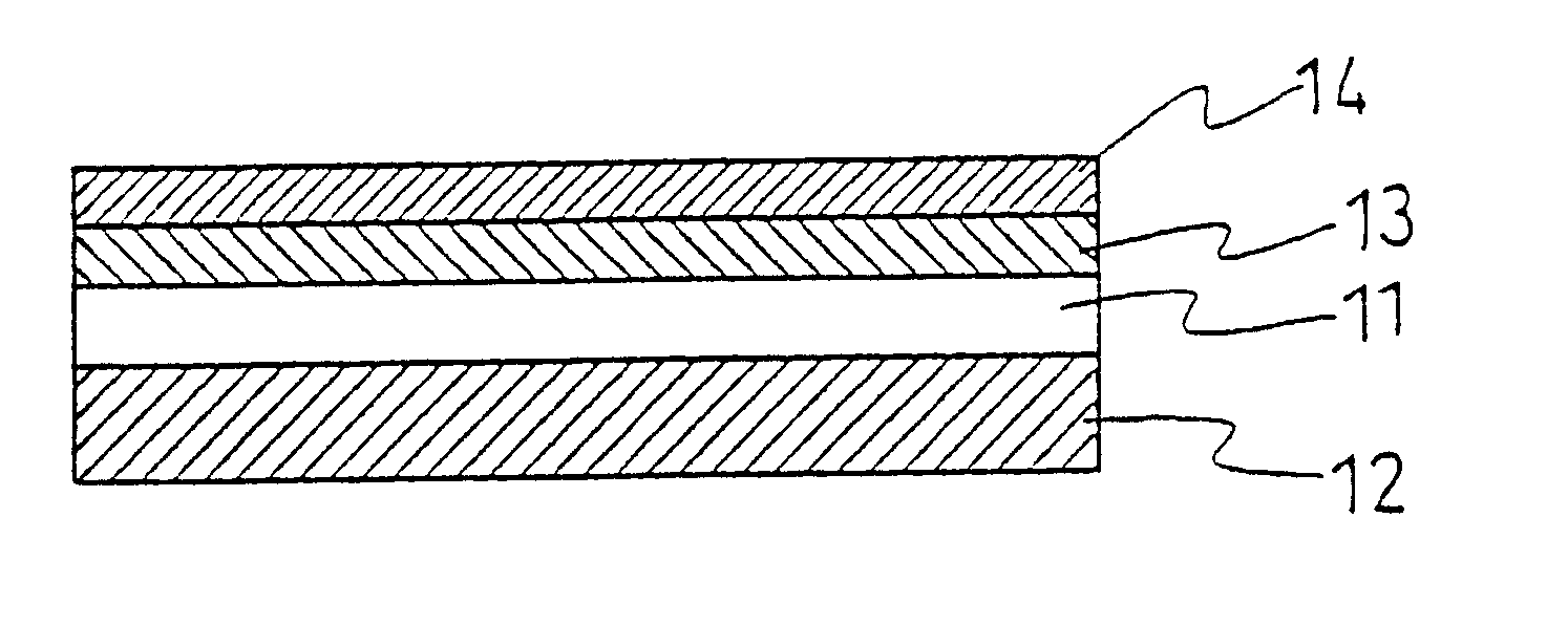
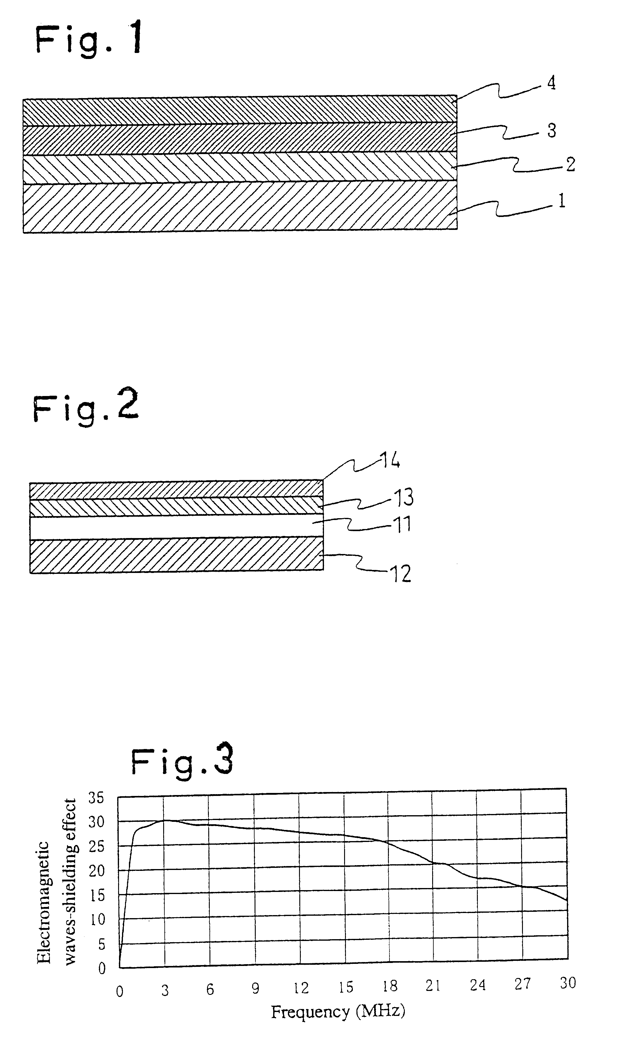
A filter for visual display terminals (VDT), comprising a substrate film having on one surface a deposition layer of indium-tin oxide (ITO) and on the other surface a flexible resin layer comprising a photopolymerized coating derived from a monomeric mixture of at least one of diallyl phthalate, diallyl isophthalate, and diallyl terephthalate, and pentaerythritol tetra(3-mercaptopropionate) in an equivalent ratio of 2:1 to 1:3, and further containing a photopolymerization initiator.

Description

The present invention relates to;an ultraviolet (UV)-curable composition for forming a coating of electronic materials, such as a surface protective layer of semiconductors, an insulating layer of semiconductor-mounted devices, a surface protective coating of color filters in liquid crystal display devices, an insulating interlayer of multilayered printed circuits and a protective coating of light guiding materials or phase shifting materials,a glass having both of the scattering-preventing properties and the anti-reflective properties, which is useful for display devices, construction materials, lenses, automobile parts, furniture and others,an adhesive agent which shows only a little aging under a high temperature and high humidity conditions, and shows an excellent adhesion property with optical films,a shock-absorbing material, such as plate glass, glass articles, potteries and others, which can protect fragile articles liable to be damaged during transportation or storage,an ea...

Claims


Application Information

Patent Timeline
Patent Type & Authority Patents(United States)
IPC IPC(8): B32B27/06C09J7/02C09J7/22C09J7/38
CPCB32B27/06C09J7/0246Y10T428/2852Y10S428/918Y10S522/912C09J2467/00C09J7/38C09J7/22Y10T428/31609Y10T428/31598Y10T428/31616Y10T428/31551Y10T428/31678Y10T428/31554B32B2377/00B32B2367/00B32B2375/00B32B7/12B32B2369/00B32B2307/416
Inventor TAKUSHIMA, HIDENORITAKESHITA, RIICHIROFUTAKI, KOUJI
Owner ASAHI KOGAKU KOGYO KK
Learn More