Enhanced electroless deposition of dielectric precursor materials for use in in-laid gate MOS transistors

a technology of dielectric precursor materials and electroless deposition, which is applied in the direction of basic electric elements, electrical equipment, and semiconductor devices, can solve the problems of reducing performance by about 15% or more, adversely affecting polysilicon gates, and increasing the effective gate oxide thickness ("eot")

Inactive Publication Date: 2002-10-15
GLOBALFOUNDRIES US INC
View PDF18 Cites 154 Cited by
  • Summary
  • Abstract
  • Description
  • Claims
  • Application Information

AI Technical Summary

Problems solved by technology

However, polysilicon-based gate electrodes incur a number of disadvantages, including, inter alia: (1) as device design rules decrease to below about 0.20 .mu.m, polysilicon gates are adversely affected by poly depletion, wherein the effective gate oxide thickness ("EOT") is increased.
Such increase in EOT can reduce performance by about 15% or more; (2) polysilicon-based gate electrodes have higher resistivities than most metal or metallic materials and thus devices including polysilicon as electrode or circuit materials operate at a much slower speed than equivalent devices utilizing metal-based materials.
Further, a significant portion of the voltage applied to the gate during operation is dropped in the polysilicon due to the poor conductivity of silicon.
The use of metal or metallic materials as replacements for polysilicon-based materials as gate electrodes in MOS and / or CMOS devices incurs several difficulties, however, which difficulties must be considered and overcome in any metal-based gate electrode process scheme, including: (1) metal and / or metal-based gates cannot withstand the higher temperatures and oxidative ambients which conventional polysilicon-based gate electrode materials can withstand; (2) several candidate metals or metallic materials for use as gate electrodes do not exhibit adequate adhesion in film form to surrounding layers of different materials when these metals or metallic materials are patterned to very small geometries; (3) some metal or metallic films are difficult to lithographically pattern and etch via conventional processing techniques because etching thereof may significantly damage underlying oxides, thereby adversely affecting device performance; and (4) thermal processing subsequent to metal gate electrode formation may result in instability and degradation of the gate oxide due to chemical interaction between the metal and oxide at the metal gate-gate oxide interface.
However, the formation (e.g., by deposition) and use of such high-k dielectric materials in the in-laid (or damascene-type) structures formed as part of the processing schemes (e.g., as shown in FIGS. 5-6 and 14-15) is difficult and problematic.
In addition, many high-k dielectric materials exhibit poor adhesion to Si and Si-based semiconductor substrate materials, as well as poor surface quality when in contact with Si-based materials.
However, all of the methods conventionally employed (or proposed) for forming such high-k dielectric layers utilize chemical vapor deposition ("CVD") or physical vapor deposition ("PVD") processes which incur a number of disadvantages and drawbacks, including: (1) energetic ion bombardment accompanying PVD-type processing resulting in degradation of the oxide / Si interface; (2) presence of free oxygen during PVD- and / or CVD-type processing resulting in unwanted reaction with Si substrate material to form low-k SiO.sub.2 -based dielectric materials; and (3) entrapment of ion bombarded species during PVD-type processing, along with associated radiation damage of the deposited high-k dielectric films.

Method used


Image

  • Enhanced electroless deposition of dielectric precursor materials for use in in-laid gate MOS transistors
  • Enhanced electroless deposition of dielectric precursor materials for use in in-laid gate MOS transistors
  • Enhanced electroless deposition of dielectric precursor materials for use in in-laid gate MOS transistors

Examples


Embodiment Construction

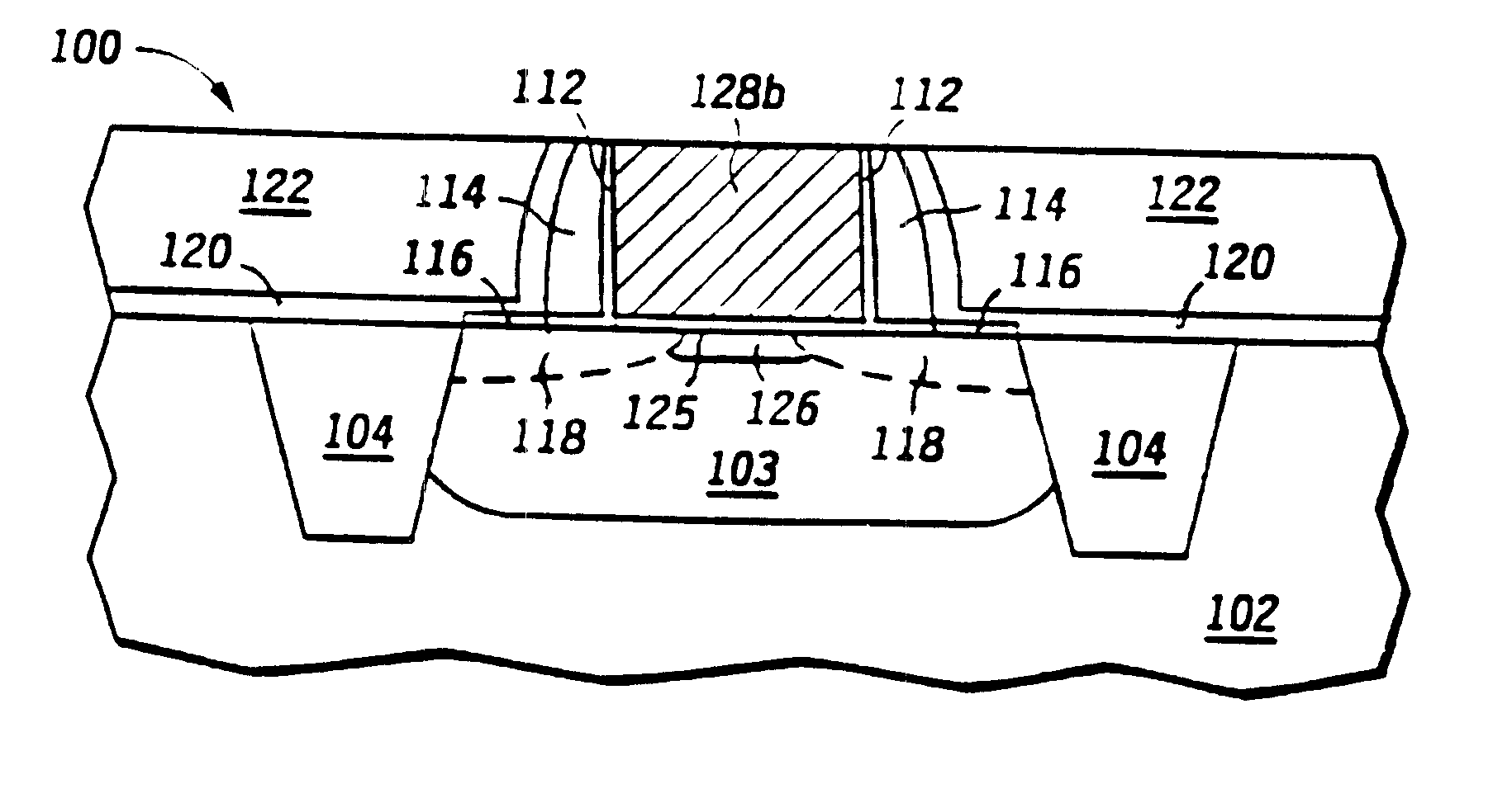
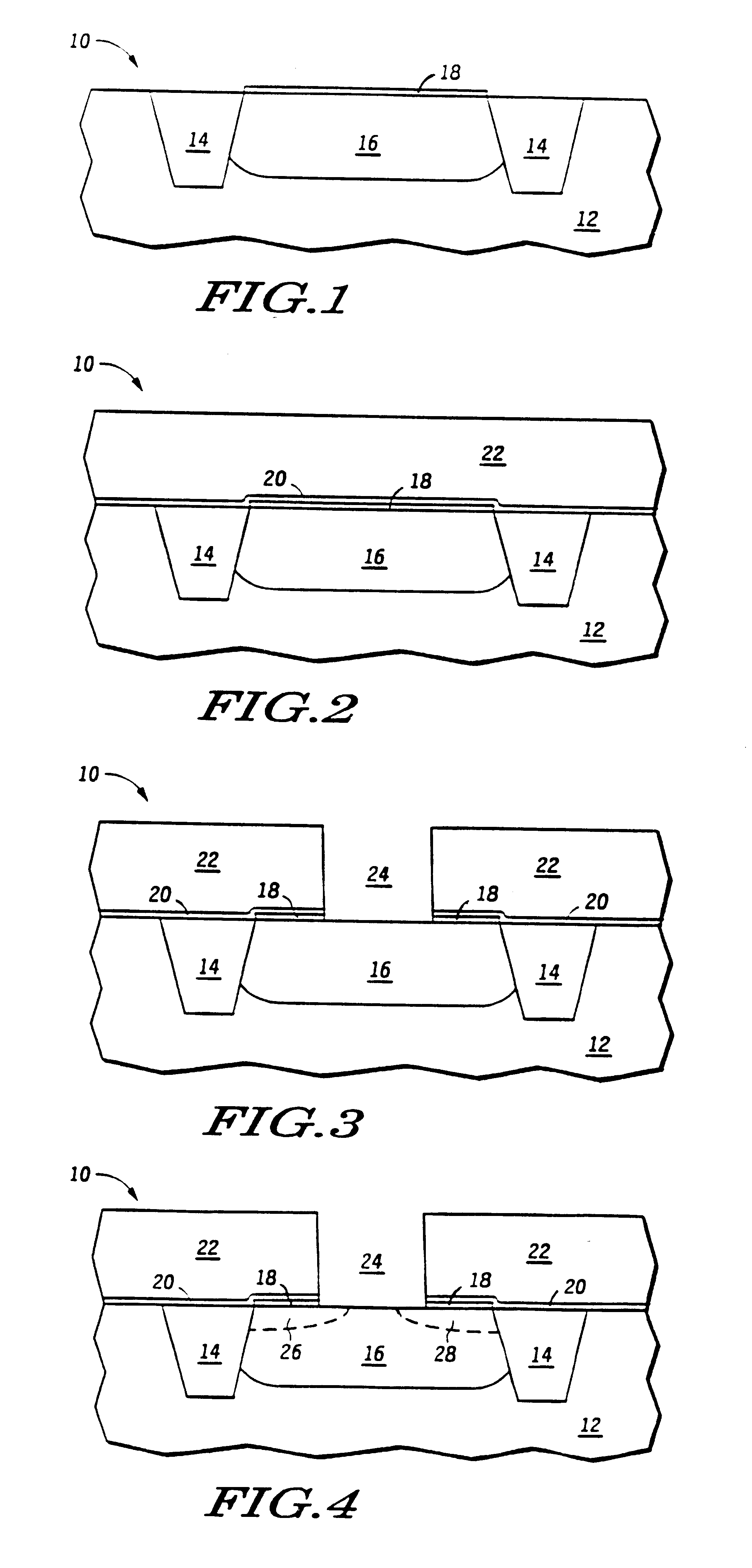
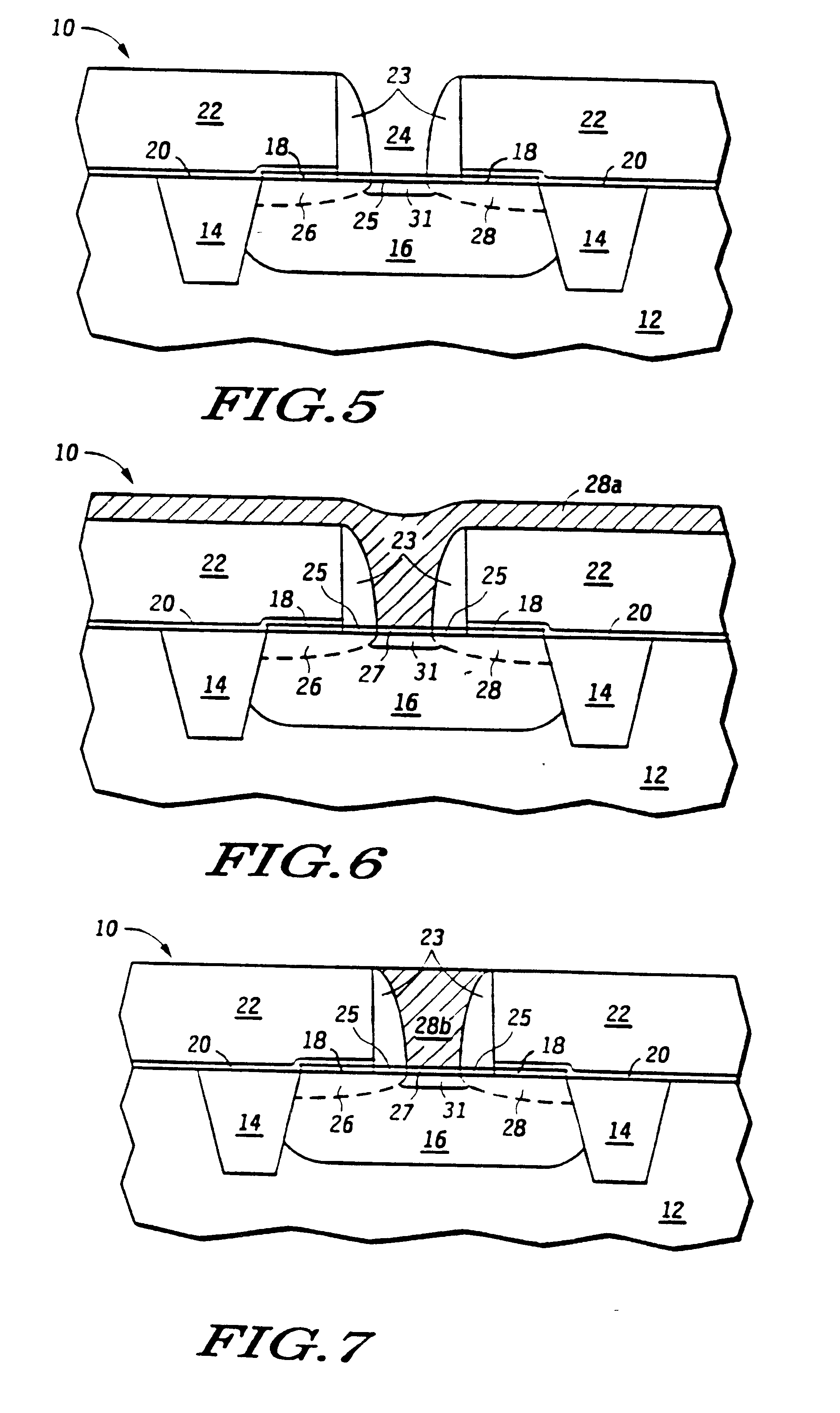
The present invention is based upon the discovery that formation of high quality dielectric layers, i.e., illustratively of, but not limited to, high-k dielectric layers comprised of at least one refractory or lanthanum series transition metal oxide or silicate, for use as gate insulator layers in in-laid gate (e.g., in-laid metal gate) MOS transistors and CMOS devices, can be readily formed by a process which prevents, or at least substantially reduces, access or exposure of the semiconductor (typically of Si but not limited thereto) substrate surface to oxygen at least during the initial stage(s) of the process. A key feature of the present invention is the formation on the substrate surface of an ultra-thin catalytic layer comprised of at least one noble metal, followed by catalyzed deposition thereon, by relatively low temperature electroless plating, of a thin layer of metal or metal-containing dielectric precursor material, e.g., a refractory metal such as of zirconium and / or ...


PUM

PropertyMeasurementUnit
thicknessaaaaaaaaaa
thickaaaaaaaaaa
thickaaaaaaaaaa

Abstract

High quality dielectric layers, e.g., high-k dielectric layers comprised of at least one refractory or lanthanum series transition metal oxide or silicate, for use as gate insulator layers in in-laid metal gate MOS transistors and CMOS devices, are fabricated by forming an ultra-thin catalytic metal layer, e.g., a monolayer thick layer of Pd or Pd, on a Si-based semiconductor substrate, electrolessly plating on the catalytic layer comprising at least one refractory or lanthanum series transition metal or metal-based dielectric precursor layer, such as of Zr and/or Hf, and then reacting the precursor layer with oxygen or with oxygen and the semiconductor substrate to form the at least one high-k metal oxide or silicate. The inventive methodology prevents, or at least substantially reduces, oxygen access to the substrate surface during at least the initial stage(s) of formation of the gate insulator layer, thereby minimizing deleterious formation of oxygen-induced surface states at the semiconductor substrate/gate insulator interface.

Description

The present invention relates to methods of manufacturing a semiconductor device, e.g., an MOS transistor device, wherein the source, drain, channel regions, and the gate electrode of the transistor are formed in a self-aligned manner utilizing an in-laid ("damascene") gate and corresponding processing techniques therefor. The present invention has particular utility in the manufacture of high integration density semiconductor devices employing design rules of 0.20 .mu.m and below, e.g., 0.15 .mu.m and below.BACKGROUND OF THE INVENTION AND RELATED ARTThe escalating requirements for high density and performance (e.g., transistor and circuit speeds) associated with ultra-large scale integration ("ULSI") devices necessitate design rules for component features of 0.20 .mu.m and below, such as 0.15 .mu.m and below, such as source, drain, and gate regions and electrodes therefor formed in or on a common semiconductor substrate, challenges the limitations of conventional materials and manu...

Claims


Application Information

Patent Timeline
Patent Type & Authority Patents(United States)
IPC IPC(8): H01L21/336H01L21/288H01L21/28H01L21/02H01L21/316H01L29/51
CPCH01L21/28194H01L21/288H01L21/31683H01L29/517H01L29/66545H01L29/66553H01L29/66583H01L21/02244H01L21/02258
Inventor BUYNOSKI, MATTHEW S.BESSER, PAUL R.KING, PAUL L.PATON, ERIC N.XIANG, QI
Owner GLOBALFOUNDRIES US INC
Why Eureka
Try Eureka