

Composite rotary tool and tool fabrication method
- Summary
- Abstract
- Description
- Claims
- Application Information
AI Technical Summary
Benefits of technology
Problems solved by technology
Method used
Image

Examples
example 1
The present example applies the method of the present invention to manufacture a novel composite cemented carbide end mill improving upon the performance of conventional end mills of a monolithic construction. As is known, conventional end milling is a relatively inefficient metal removal technique because the end of the tool is not supported, and the tool's length-to-diameter ratio is typically large. This can result in excessive bending of the end mill and, therefore, low depths of cut, feed rates, and cutting speeds are usually employed. A composite end mill constructed according to the present invention may include a relatively stiff inner core region with a high modulus of elasticity to resist bending, and a relatively strong and tough outer region suitable for end milling applications.
In the present example, the end mill was provided with two coaxially disposed regions. The inner core region exhibits a high modulus of elasticity and, therefore, Teledyne (Lavergne, Tennessee) g...
example 2
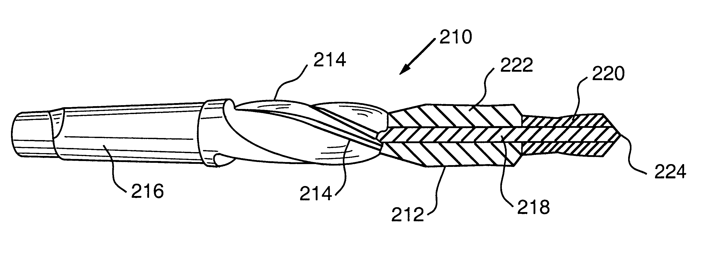
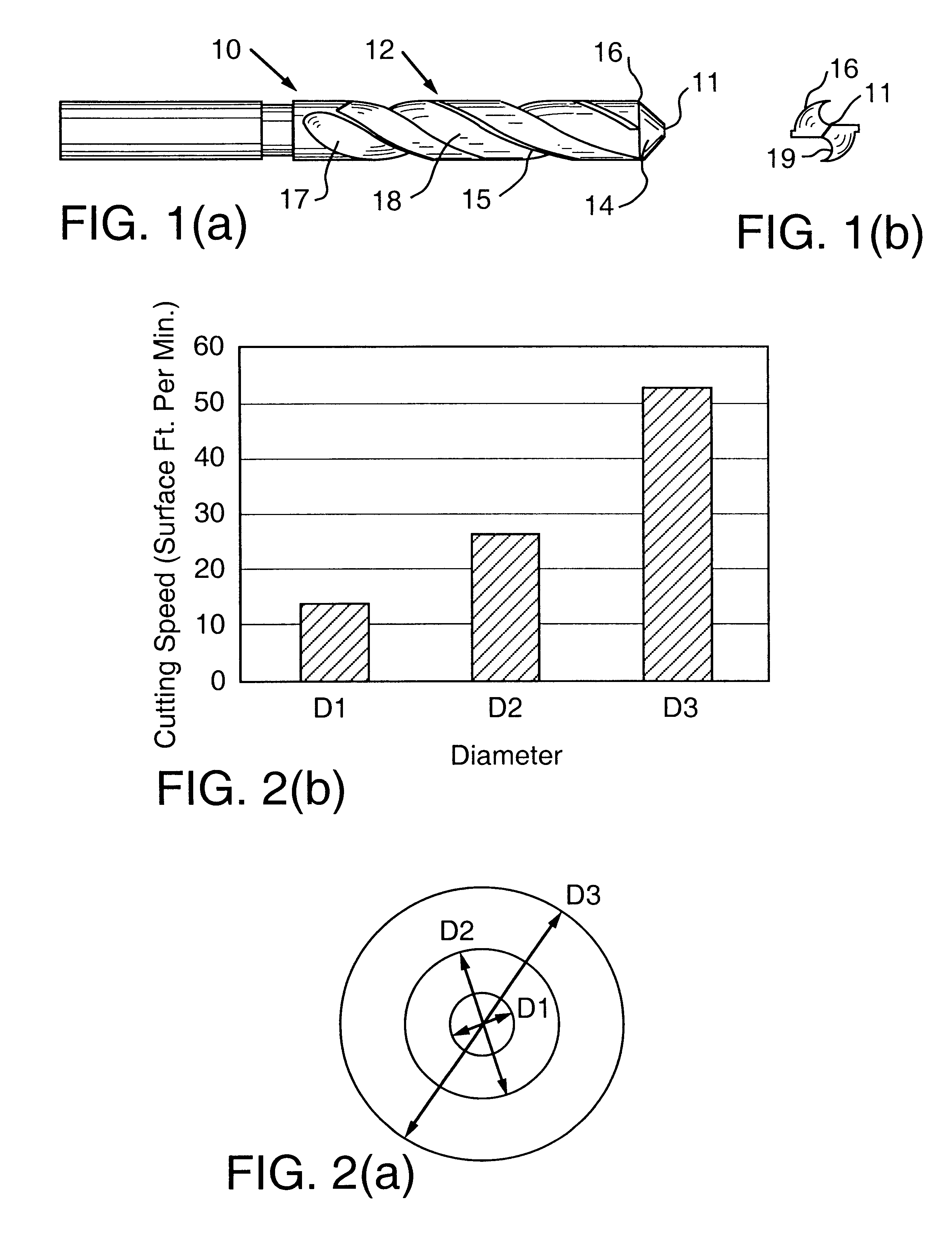
The present example applies the method of the present invention to manufacture a novel composite cemented carbide drill improving upon the performance of conventional drills of a monolithic construction. As shown in FIG. 1, the initial cut into the workpiece is made by the drill's chisel edge at a relatively small diameter on the drill's cutting edge. Also, as shown in FIGS. 2(a) and (b), the cutting speed is much slower at smaller diameters on the cutting edge. The inner core of the drill is thus expected to remove the bulk of the material at slow speeds (rough cutting) while the outer diameters of the cutting edge perform the finish cutting. This can result in the excessive build-up of heat in the center of the drill, resulting in premature thermal cracking. In addition, the core region can be expected to chip and fracture at a faster rate compared with the outer region. In order to obtain uniform chipping and wear, it is thus advantageous to have slightly softer and tougher (and ...
example 3
The rotary tools in Examples 1 and 2 included regions of cemented carbide grades differing in cobalt binder content. The tungsten carbide grain sizes in the regions, however, were approximately the same. In the present example, a rotary tool blank in the form of a composite rod was provided by combining cemented carbide grades differing in binder content and average tungsten carbide grain size. A first region of the composite rod was composed of Teledyne grade H-17, which has a fine carbide grain structure. (Grade H-17 has an average grain size of approximately 0.8 microns, a cobalt content of 10.0 weight percent, and a hardness of 91.7 HRA.) A second region of the composite rod was composed of Teledyne grade R-61, which has a coarse carbide grain structure. (Grade R-61 has an average grain size of approximately 4.0 microns, a cobalt content of 15.0 weight percent, and a hardness of 86.0 HRA.) The composite rod was fabricated by substantially the same methods as used in Examples 1 a...
PUM
| Property | Measurement | Unit |
|---|---|---|
| Fraction | aaaaa | aaaaa |
| Fraction | aaaaa | aaaaa |
| Fraction | aaaaa | aaaaa |
Abstract
Description
Claims
Application Information