Stable high rate reactive sputtering

a sputtering and high-rate technology, applied in the field of sputtering, can solve the problems of low deposition rate, preventing high-throughput production, excessive substrate heating,

Inactive Publication Date: 2003-03-25
VEECO INSTR
View PDF5 Cites 98 Cited by
  • Summary
  • Abstract
  • Description
  • Claims
  • Application Information

AI Technical Summary

Problems solved by technology

However, their extremely low deposition rate prevents high-throughput production.
Further, excessive substrate heating and poor thickness uniformity are normally associated with RF diode processes.
However, high-rate reactive sputtering near the metal mode is usually very unstable due to the poisoning of the target by the arriving oxygen or nitrogen.
Any deviation from the equilibrium between the arrival and removal rates of oxygen at the target surface tends to escalate rapidly and result in a drastic drift towards the unwanted metal mode or the low-rate oxide mode.
Due to the "inertia" associated with pressure changes, partial pressure control appears not fast enough to correct the instability buildup during the deposition process.
Too radical adjustment of partial pressure tends to overshoot and cause instability in the opposite direction.
Moreover, the precision of partial pressure control may not be sufficient enough to match the subtle deviation from the balanced operating state.
Other approaches include low-frequency modulation of discharge current and even pulsed DC power, but they are unable to follow the instant and random fluctuations near the operating point.
Such compound deposition and formation at the target is well recognized as a primary problem in reactive sputtering, and is particularly a problem in reactive sputtering of non-insulating (e.g., conductive or semiconductive) targets to produce substantially non-conducting (e.g., very low conductivity or insulating or dielectric) compounds.
At lower oxygen flow rates away from the transition point the film might be partially metallic (absorbing), while it is usually nearly impossible to achieve stability at or along the transition zone with traditional partial pressure or flow control.
At higher oxygen flow rates away from the sharp decreasing transition region, the deposition rate is very low and therefore this region is generally undesirable.

Method used


Image

  • Stable high rate reactive sputtering
  • Stable high rate reactive sputtering
  • Stable high rate reactive sputtering

Examples


Embodiment Construction

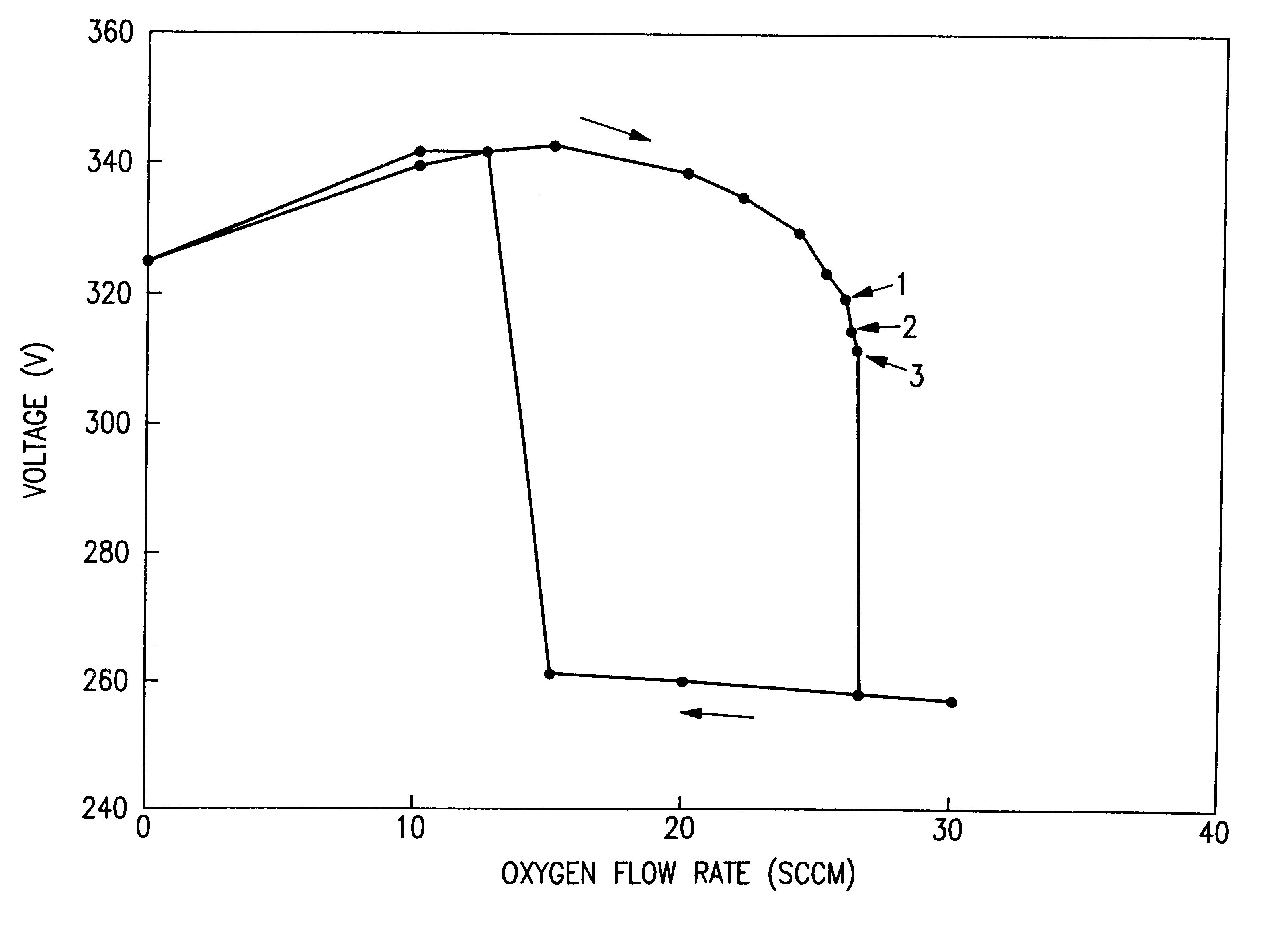
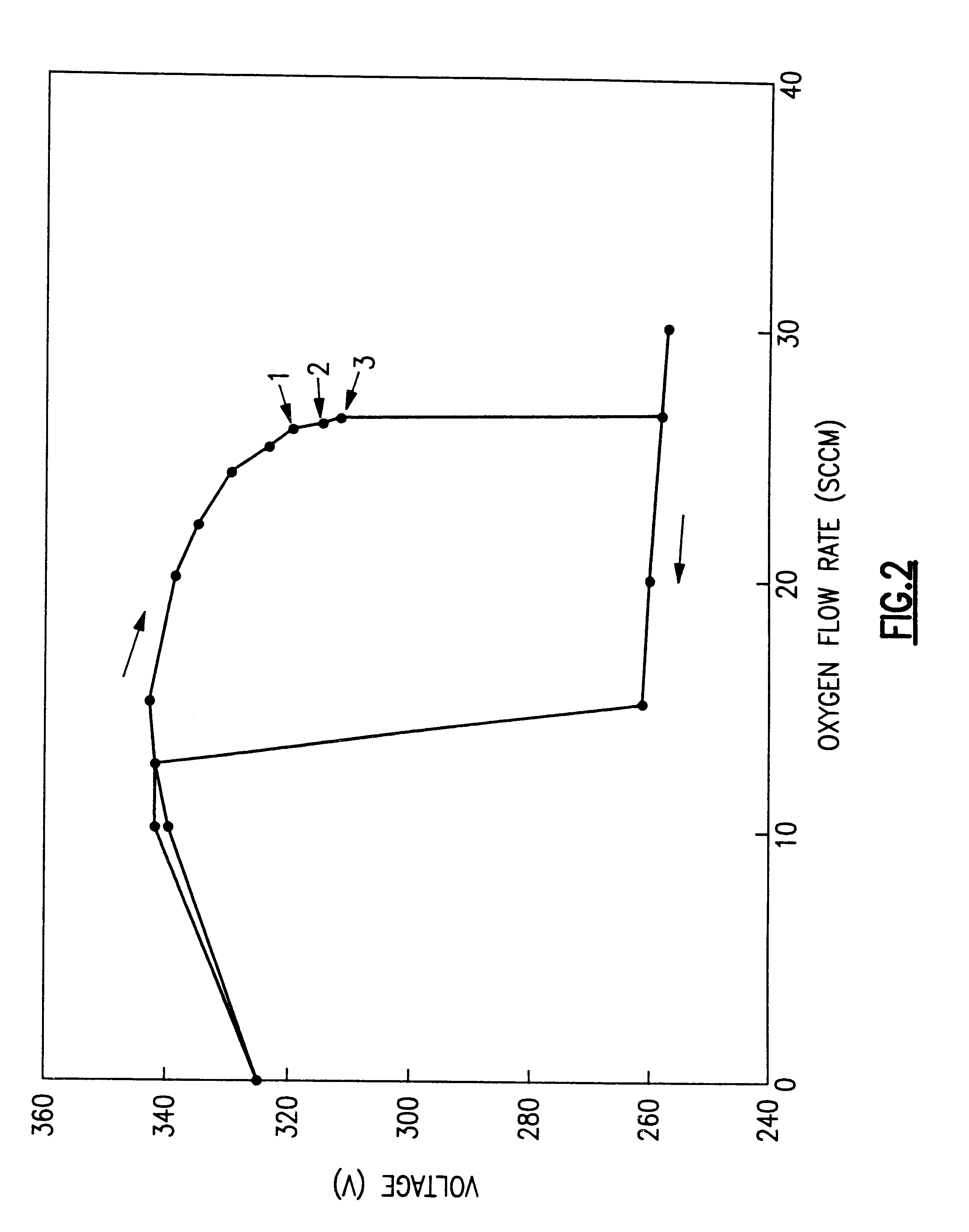
The hysteresis curve shown in FIG. 2 was measured for a nominal DC power of 5 KW, and a total volumetric gas flow rate (i.e., argon and oxygen) of 200 sccm, using a Veeco Instruments Cymetra.TM. sputtering system. This system included separate gas rings for O2 and argon to minimize the poisoning of target surface by oxygen. In addition, a choke-off plate was placed between the target and substrate to reduce the arrival rate of metallic atoms sputtered off the target and reaching the substrate. Moreover, a rotating magnetron magnet pack, such as the RMX.TM. type cathode, was used to ensure full-face erosion on the target surface and hence to minimize target poisoning due to oxygen in areas of low or zero sputtering. Further an ENI RPG-100 power supply (which is a DC power supply with high frequency current polarity reversal capability) capable of pulsing at frequencies up to 200 kHz was used in conjunction with an Advanced Energy SPARC-LE-20 arc suppression unit to minimize arcing du...


PUM

PropertyMeasurementUnit
diameteraaaaaaaaaa
frequenciesaaaaaaaaaa
thicknessaaaaaaaaaa

Abstract

A method and apparatus for monitoring and controlling reactive sputter deposition, particularly useful for depositing insulating compounds (e.g., metal-oxides, metal-nitrides, etc.). For a given nominal cathode power level, target material, and source gases, the power supplied to the cathode (target) is controlled to stabilize the cathode (target) voltage at a specified value or within a specified range corresponding to a partial pressure or relative flow rate value or range of the reactive gas. Such an operating point or range, characterized by a specified voltage value or range and corresponding reactive gas relative-flow/partial-pressure value or range, may be determined empirically based on measuring the cathode voltage as a function of reactive gas relative-flow/partial-pressure for the given nominal power. This relationship is typically a hysteresis curve, and preferably the operation point is selected at or near the hysteresis transition edge to provide high rate deposition of high quality films, including insulating or dielectric films using a metallic target.

Description

1. Technical FieldThe present invention relates generally to sputtering, and more particularly to a reactive sputtering method and system for stabilizing the reactive sputtering process through sputter power control to balance the arrival and removal rates of reactive species at target surface for high-rate deposition of dielectric films.2. Background ArtDielectric and other non-conducting films are widely used in a broad range of applications such as semiconductor chips, magnetic and optical recording, flat panel displays, ink jet printer heads, solar cells, integrated optics, optical coatings, etc. Traditional deposition methods like RF diode and RF magnetron sputtering using a dielectric target have been well established and commonly used by the industries. However, their extremely low deposition rate prevents high-throughput production. Further, excessive substrate heating and poor thickness uniformity are normally associated with RF diode processes.As an alternative, reactive s...

Claims


Application Information

Patent Timeline
Patent Type & Authority Patents(United States)
IPC IPC(8): C23C14/54C23C14/00H01J37/34H01J37/32
CPCC23C14/0036C23C14/0094H01J37/3444H01J37/34C23C14/54
Inventor XIONG, WEIGUPTA, SUBHADRA
Owner VEECO INSTR
Why Eureka
Try Eureka