
Exhaust gas purifying catalyst and method of producing same

a technology of exhaust gas purification and purification catalyst, which is applied in the direction of physical/chemical process catalyst, metal/metal-oxide/metal-hydroxide catalyst, and separation process, etc., can solve the problem that the adsorption catalyst cannot function as an exhaust gas purification catalyst, the oxidizing efficiency of the released hc is sharply lowered, and the production cost of the system increases. , to achieve the effect of purifying exhaust gas for a long time period

Inactive Publication Date: 2003-07-08
NISSAN MOTOR CO LTD
View PDF17 Cites 72 Cited by
  • Summary
  • Abstract
  • Description
  • Claims
  • Application Information

AI Technical Summary

Benefits of technology

Besides, it is effective to increase the Si / 2Al ratio of zeolite and introduce polyvalent metal into the zeolite frame in order to improve heat resistance of zeolite. However, use of a high silica zeolite increases a hydrophobic property of surface of zeolite particles thereby largely lowering a bonding ability of zeolite particles with an inorganic binder. Accordingly, zeolite unavoidably separates and settles in an aqueous slurry thereby degrading a coating characteristics of the slurry. Additionally, after a long time use, the bonding force between the HC adsorbing material layer and the three-way catalyst component layer is sharply lowered so that the three-way catalyst component layer may peels off from and separates from the substrate. As a result, it is impossible to equally effectively remove all of HC, CO and NOx.
However, these measures make the exhaust gas purifying systems complicated while sharply increasing production cost of the systems although sufficient effects for equally removing HC, CO and NOx cannot be obtained. Thus, development of the HC adsorbing material which is high in durability and HC adsorbing ability has been eagerly desired.
It is an object of the present invention to provide an improved exhaust gas purifying catalyst and a method of producing the same catalyst, which can effectively overcome drawbacks encountered in conventional exhaust gas purifying catalysts.
Another object of the present invention is to provide an improved exhaust gas purifying catalyst and a method of producing the same catalyst, which can effectively purify exhaust gas throughout a long period of time.
Another object of the present invention is to provide an improved exhaust gas purifying catalyst and a method of producing the same catalyst, which can effectively oxidize or remove a high concentration of HC emitted in a cold engine operation range or immediately after engine starting while effectively preventing a HC adsorbing material (HC adsorbing catalyst component) from peeling off and separating from a substrate even after a long time use of the exhaust gas purifying catalyst.

Problems solved by technology

However, with the above conventional HC adsorbing catalysts, when the crystal structure of zeolite is broken and deformation of pores in zeolite is promoted in the HC adsorbing material layer after a long time use, the absorbed HC is unavoidably released from zeolite before the three-way catalyst components in the three-way catalyst component layer as an upper layer is activated.
Consequently, the oxidizing efficiency for the released HC is sharply lowered so that the HC adsorbing catalyst cannot function as an exhaust gas purifying catalyst.
However, use of a high silica zeolite increases a hydrophobic property of surface of zeolite particles thereby largely lowering a bonding ability of zeolite particles with an inorganic binder.
Accordingly, zeolite unavoidably separates and settles in an aqueous slurry thereby degrading a coating characteristics of the slurry.
As a result, it is impossible to equally effectively remove all of HC, CO and NOx.
Furthermore, with exhaust gas purifying systems including the HC adsorbing catalyst disclosed in the above Japanese Provisional Publications, the durability of the HC adsorbing material is insufficient, and therefore a HC adsorbing ability of the HC adsorbing material is lowered after a long time use.
However, these measures make the exhaust gas purifying systems complicated while sharply increasing production cost of the systems although sufficient effects for equally removing HC, CO and NOx cannot be obtained.

Method used


Image

  • Exhaust gas purifying catalyst and method of producing same
  • Exhaust gas purifying catalyst and method of producing same
  • Exhaust gas purifying catalyst and method of producing same

Examples


example 1

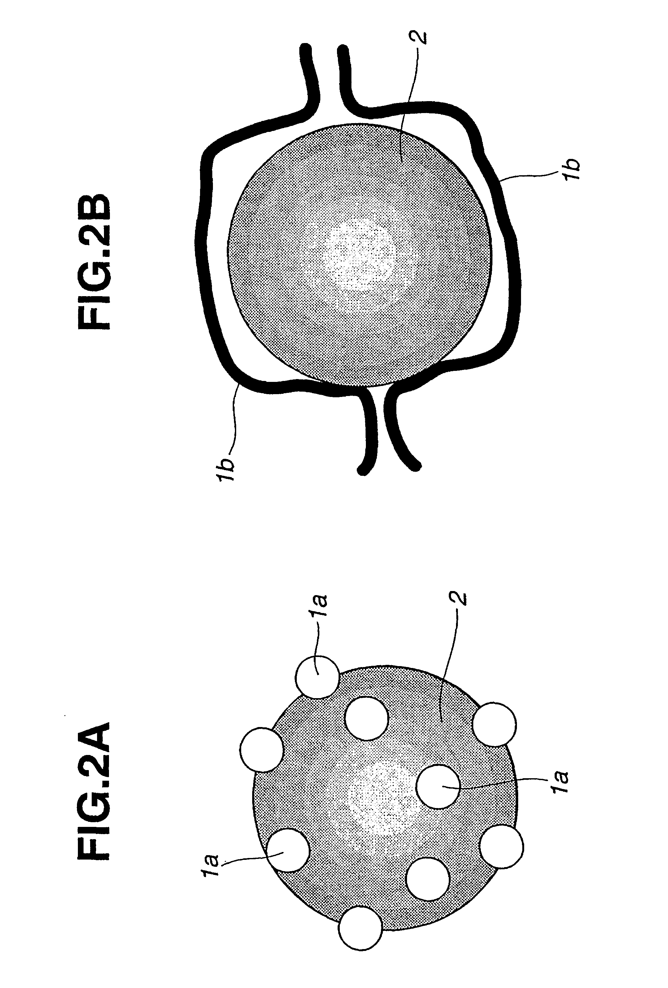
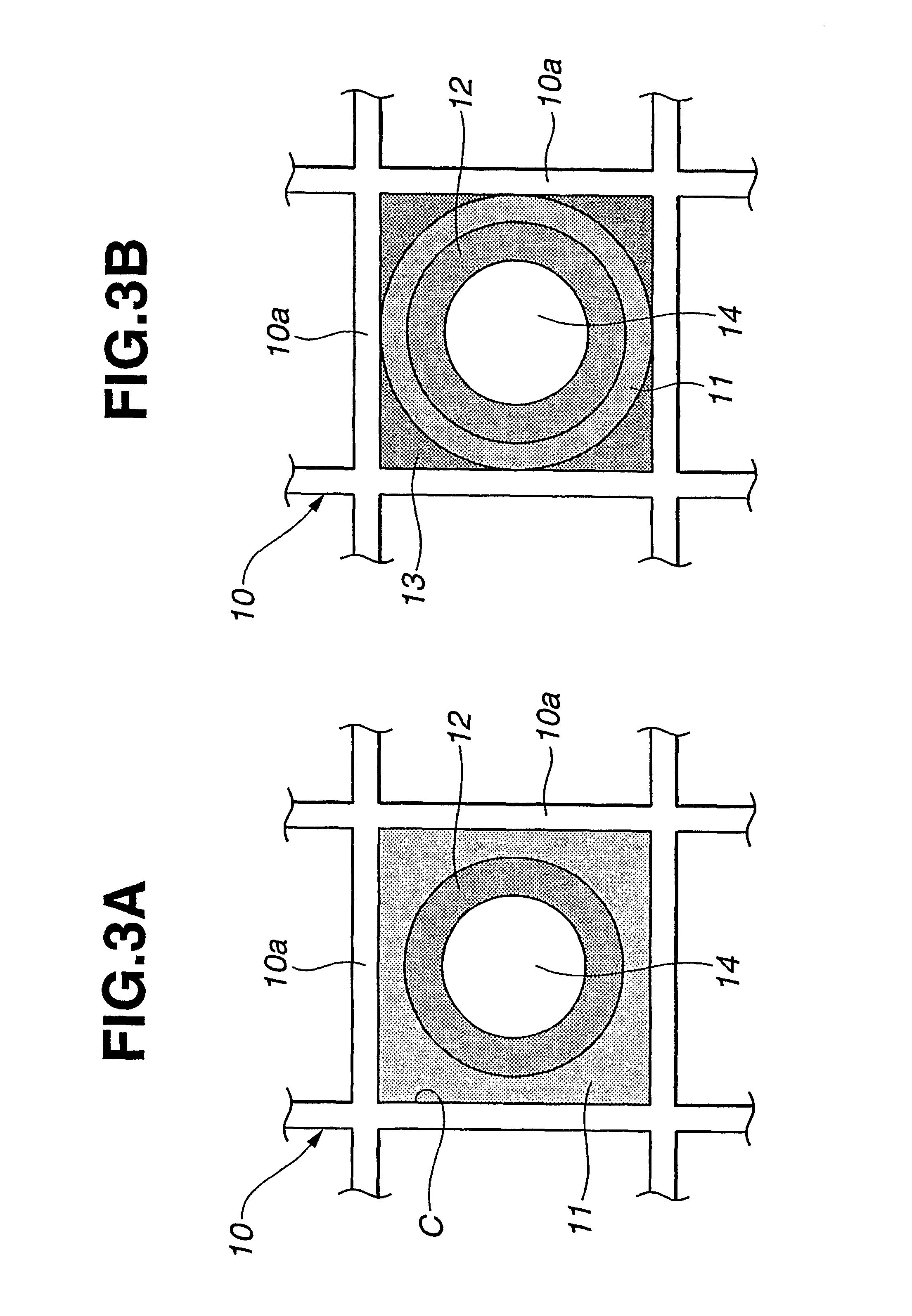
A porcelain ball mill was charged with 475 g of .beta.-zeolite powder (Si / 2Al=50), 125 g of colloidal silica (having a solid content of 20% by weight and having a trade name of ST-UP and produced by Nissan Chemical Industries, Ltd.) whose particles were chain and whose average particle size was within a range of from 40 to 100 nm, and 1000 g of pure water, followed by mixing and pulverization, thereby obtaining a slurry. This slurry was coated on a cordierite ceramic honeycomb-type monolithic substrate having a volume of 1.3 liters, 600 (axially extending) cells per square inch and having a thickness of walls (defining each cell) of 4 mil, so that thin walls of cells were coated with the slurry. Thereafter, the coated monolithic substrate was blown with air stream to remove excessive slurry in the cells, and dried and then fired at 400.degree. C. for 1 hour, thereby forming a coat layer (zeolite-base layer). The above procedure from coating to calcining was repeated until the weight...

example 2

A porcelain ball mill was charged with 400 g of .gamma.-alumina, 1000 g of nitric acid-acidic alumina sol (prepared by adding 10% (wt) nitric acid to 10% by weight of boehmite alumina) and 500 g of pure water, followed by mixing and pulverizing, thereby obtaining a slurry. This slurry was coated on a cordierite ceramic honeycomb-type monolithic substrate having a volume of 1.3 liters, 600 (axially extending) cells per square inch and having a thickness of walls (defining each cell) of 4 mil, so that thin walls of cells were coated with the slurry. Thereafter, the coated monolithic substrate was blown with air stream to remove excessive slurry in the cells, and dried and then fired at 400.degree. C. for 1 hour, thereby forming a coat layer (alumina-base layer). The above procedure from coating to calcining was repeated until the weight of the coat layer became 100 g per one liter of the monolithic substrate after calcining. Thus, a catalyst 2a was prepared.

A porcelain ball mill was c...

example 3

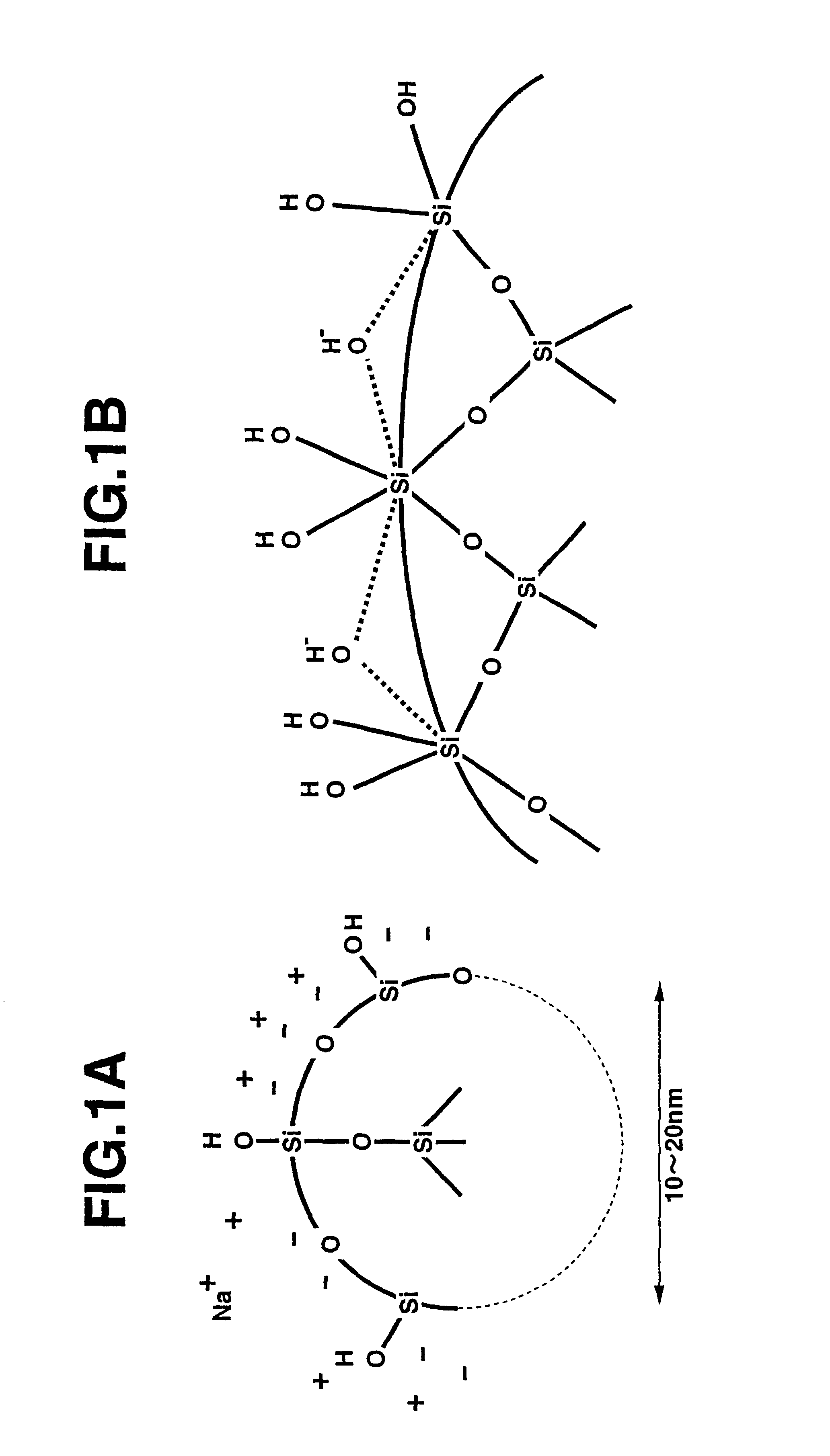
An exhaust gas purifying catalyst of Example 3 was produced by repeating the procedure of Example 1 with the exception that 450 g of .beta.-zeolite powder (Si / 2Al=25), 200 g of colloidal silica (having a solid content of 20% by weight and having a trade name of ST-UP and produced by Nissan Chemical Industries, Ltd.) whose particles were chain and whose average particle size was within a range of from 40 to 100 nm, and 50 g of colloidal silica (having a solid content of 20% by weight and having a trade name of ST-O and produced by Nissan Chemical Industries, Ltd.) whose particles were spherical and whose average particle size was within a range of from 10 to 20 nm were used in place of .beta.-zeolite powder and colloidal silica in Example 1.


PUM

PropertyMeasurementUnit
particle sizeaaaaaaaaaa
specific surface areaaaaaaaaaaa
particle sizeaaaaaaaaaa

Abstract

An exhaust gas purifying catalyst for exhaust gas discharged from an automotive internal combustion engine. The catalyst comprises a substrate over which a hydrocarbons adsorbing material layer is formed as a lower layer to absorb hydrocarbons contained in exhaust gas. The hydrocarbons adsorbing material layer contains zeolite and colloidal silica which has undergone firing. The colloidal silica is in a chain-like form and / or a spherical form before and after the firing. Additionally, a catalyst component layer is formed as an upper layer over the hydrocarbons adsorbing material layer. The catalyst component layer contains a catalyst metal.

Description

This invention relates to improvements in an exhaust gas purifying catalyst and a method of producing the same, and more particularly to the exhaust gas purifying catalyst for purifying exhaust gas discharged from an internal combustion engine so as to remove hydrocarbons (IC), carbon monoxide (CO) and nitrogen oxides (NOx) contained in exhaust gas, particularly effectively removing hydrocarbons. The exhaust gas purifying catalyst is effective, for example, for purifying exhaust gas discharged from the engine of an automotive vehicle or the like in a cold engine operation range (where exhaust gas temperature is low) immediately after engine starting, particularly removing hydrocarbons at a high efficiency.In recent years, a so-called HC adsorbing catalyst has been developed for the purpose of removing a large amount of hydrocarbons generated in a low engine temperature range during engine starting of an internal combustion engine. The HC adsorbing catalyst includes a HC adsorbing ma...

Claims


Application Information

Patent Timeline
Patent Type & Authority Patents(United States)
IPC IPC(8): B01J23/63B01D53/94B01J23/54B01J35/00B01J37/02B01J37/00B01J35/02B01J23/56F01N3/08B01J29/068F01N3/10F01N3/24
CPCB01D53/945B01D53/9486B01J23/63B01J35/0013B01J35/023B01J37/0244B01J37/0246B01D2255/1021B01D2255/1023B01D2255/1025B01D2255/202B01D2255/204B01J23/56B01J2229/42Y02T10/22Y02T10/12B01J35/23B01J35/40B01J20/28B01J35/56
Inventor YAMAMOTO, SHINJITAKAYA, MASAHIRO
Owner NISSAN MOTOR CO LTD
Learn More