Radar for detecting the distance to a target

a technology for detecting distance and target, which is applied in the direction of reradiation, measurement devices, instruments, etc., can solve the problems of increasing the overall size, incurring additional costs, and unable to achieve sufficient agc against an instantaneous change in the strength of reception signals

Inactive Publication Date: 2003-07-15
MURATA MFG CO LTD
View PDF17 Cites 11 Cited by
  • Summary
  • Abstract
  • Description
  • Claims
  • Application Information

AI Technical Summary

Benefits of technology

Accordingly, the frequency range of a signal which is input to the amplifier circuit is restricted, so that the SN ratio is improved.
Accordingly, undesirable effects of the DC component and noise signal components in the vicinity of DC, superposed on the IF signal, are avoided, preventing reduction in sensitivity, degradation of SN ratio, and erroneous detection.
Accordingly, as opposed to the related art, complex circuitry such as an AGC circuit is not required, serving to reduce the overall size and cost. Furthermore, unlike AGC circuits, an instantaneous change in the strength of the reception signal can be properly dealt with.
Accordingly, the gain at short distances are made relatively larger so as to improve sensitivity, whereby the problem of relative insufficiency in sensitivity at short distances due to a saturation of the mixer is prevented. Thus, a target at a short distance can be accurately detected.

Problems solved by technology

However, if the gain of the amplifier circuit is too large, when a signal received from a short distance is amplified, the amplified signal exceeds the input range of an analog to distal (AD) converter, causing an overflow.
However, such an AGC capability can only be implemented by adding complex circuitry, increasing the overall size and incurring additional cost.
Furthermore, because AGC is usually achieved by a loop or feedback control, a sufficient AGC is not achieved against an instantaneous change in the strength of reception signal due to the effect of the time constant of the control loop.
If a frequency component at or above one half of the sampling frequency is present in an input signal to the AD converter, a problem occurs.
That is, the frequency components at or above one half of the sampling frequency are folded over and superposed on the frequency components lower than the center frequency of the sampling frequency, causing a detection of a false image.
Furthermore, in the lower range of IF frequencies corresponding to short distances, the gain is decreased, inhibiting detection of small targets.
Furthermore, the radars disclosed in (4) and (5) do not specify how to handle DC components and low-frequency components in the vicinity of DC in the IF signal.
Furthermore, a high-frequency signal generated by a voltage-controlled oscillator VCO for generating a transmission signal causes noise signals in the vicinity of the carrier frequency, due to thermal noise, flicker noise in semiconductors, etc.
The DC and the noise signal in the vicinity of DC, superposed on the IF signal, may reduce the sensitivity of the radar, degrade SN ratio, and cause an erroneous detection.

Method used


Image

  • Radar for detecting the distance to a target
  • Radar for detecting the distance to a target
  • Radar for detecting the distance to a target

Examples


first embodiment

The construction of a radar will now be described with reference to FIGS. 1 to 5.

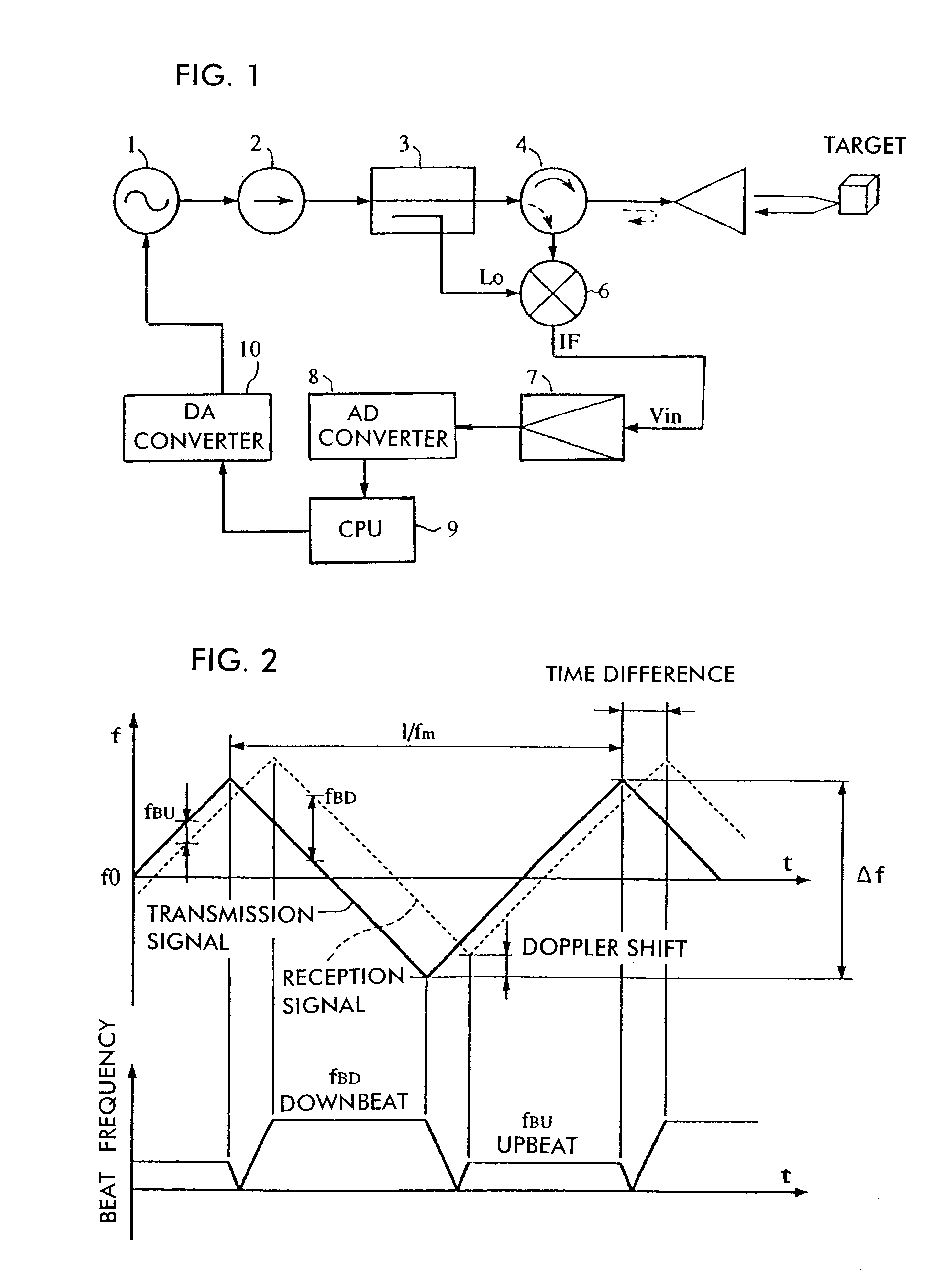
FIG. 1 is a block diagram showing the overall construction of the radar. Referring to FIG. 1, a voltage-controlled oscillator VCO1 changes the oscillation frequency in accordance with a control voltage output from a DA converter 10. An isolator 2 transmits an oscillation signal from the VCO1 to a coupler 3, inhibiting a reflection signal from being input to the VCO1. The coupler 3 transmits a signal from the isolator 2 to a circulator 4, and feeds a predetermined ratio of a transmission signal to a mixer 6 as a local signal Lo. The circulator 4 transmits the transmission signal to an antenna 5, and feeds a reception signal from the antenna 5 to the mixer 6.

The antenna 5 transmits the continuous-wave transmission signal frequency modulated by the VCO1, and receives a reflection signal from the same direction. The antenna 5 also periodically changes the direction of beams over a range of detection angle....

second embodiment

Next, the construction of a radar will be described with reference to FIGS. 6 to 8.

FIG. 6 shows an example of variation in input signal Vin to the IF amplifier circuit 7 shown in FIG. 1 in relation to the distance R of a target from an antenna. As shown in FIG. 6, the level of reception signal varies in accordance with the size of the target, such as a large-sized car, a standard-sized car, and a motorbike. The input signal Vin also varies accordingly at a gradient of 1 / R.sup.4. However, when a reflection signal from a nearby target is received, in the case of a large-sized car, at a distance nearer than a distance Ra, as the level of reception signal increases, a saturation is caused due to the characteristics of the mixer 6, causing the gradient of Vin relative to the distance R to be less steep than 1 / R.sup.4. Thus, if the gain monotonously increases as the frequency rises as in the related art, a sufficient sensitivity is not achieved at short distances, namely when receiving l...

third embodiment

Next, the construction of a radar will be described with reference to FIGS. 9 and 10.

FIG. 9 shows an example of the gain-frequency characteristics of an IF amplifier circuit. Although characteristics at zero frequency, i.e., DC, and in the vicinity thereof are not shown in FIG. 7, as already described in the related art section, DC component or components in the vicinity thereof, if included in an IF signal, may degrade sensitivity, deteriorate SN ratio, and cause an erroneous detection. Thus, as shown in FIG. 9, the characteristics are such that the gain is zero at DC and the gain is decreased at frequencies lower than the frequency f.sub.IFmin of an IF signal corresponding to a minimum (shortest) detection distance.

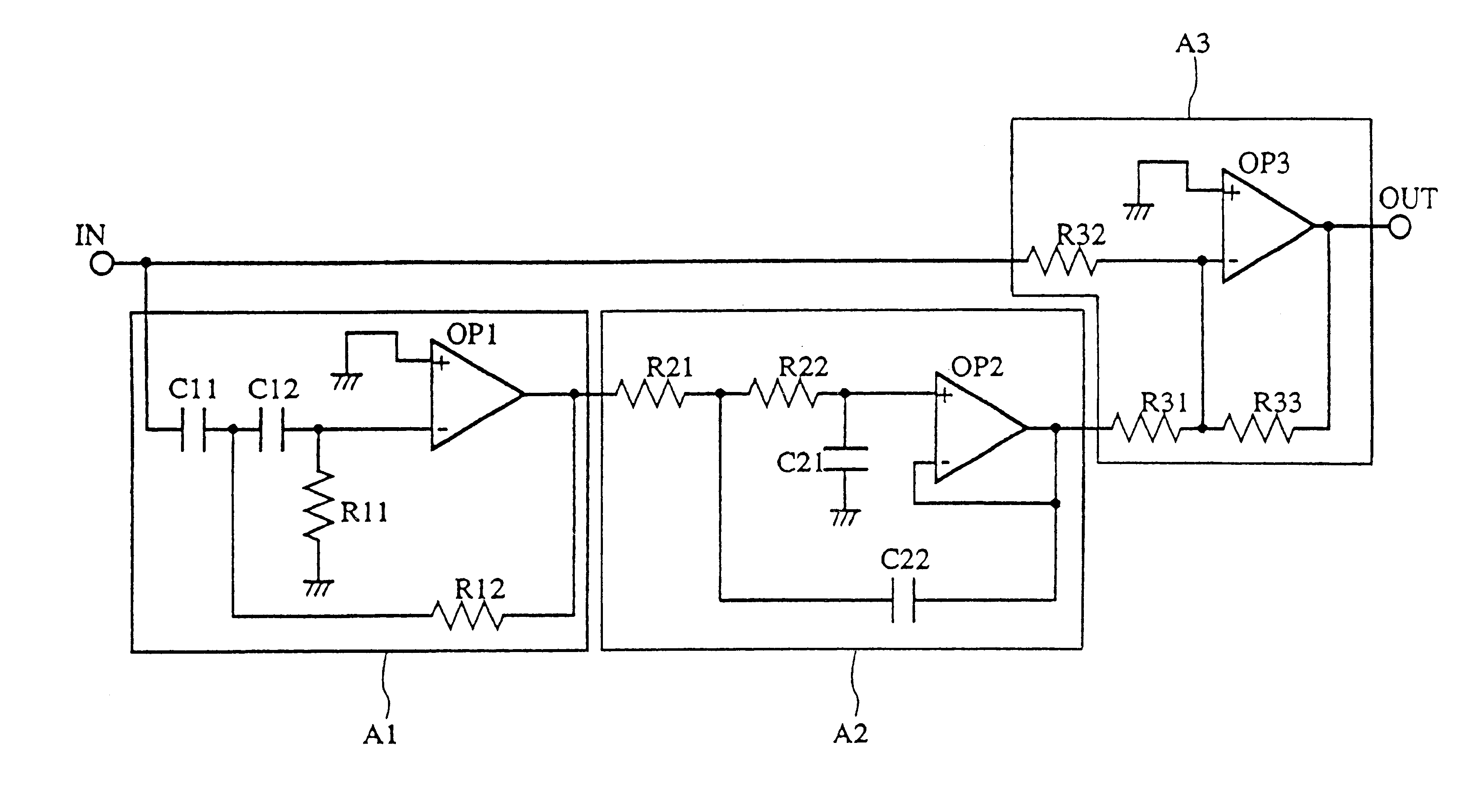
FIG. 10 shows an example implementation of an IF amplifier circuit which exhibits the gain-frequency characteristics shown in FIG. 9. In FIG. 10, A4 is a circuit comprising capacitors C41 and C42 and a resistor R41, which attenuates lower frequencies. The constructions...


PUM


Abstract

In a radar, a frequency-modulated transmission signal whose frequency varies in time is generated. The gain-frequency characteristics of an IF signal which represents a beat signal between the transmission signal and a reception signal has its peak at or below one half of the sampling frequency of an AD converter. The gain-frequency characteristics of an IF amplifier circuit is determined so that the gain increases as the frequency increases at or below the frequency corresponding to the peak, the ratio of change in the gain relative to change in the frequency becomes smaller at short distances for which a saturation of a mixer is caused, and the gain is reduced at DC and in the vicinity of DC.

Description

1. Field of the InventionThe present invention relates to a radar for detecting a vehicle, etc. using, for example, electromagnetic waves in the millimeter-wave band.2. Description of the Related ArtGenerally, the strength S of a reception signal received by a radar varies in accordance with distance. The relationship between the strength S of a signal received by a radar and the distance can be expressed by the following radar equation:S=(PG.sup.2.lambda..sup.2.sigma.) / ((4.pi.).sup.3 R.sup.4.times.L)where P denotes the output power, G denotes the antenna gain, .lambda. denotes the wavelength, .sigma. denotes the scattering cross-section, R denotes the distance, and L denotes the propagation loss.Thus, the strength S of a signal received by a radar is inversely proportional to R.sup.4 ; therefore, when the radar is used over a large range from a short distance to a long distance, the strength S varies in a wide range in accordance with the distance of a target from an antenna.A beat...

Claims


Application Information

Patent Timeline
Patent Type & Authority Patents(United States)
IPC IPC(8): G01S13/00G01S13/34G01S13/93G01S13/58G01S7/02G01S7/35G01S7/285G01S13/931
CPCG01S7/354G01S13/345G01S13/584G01S13/931G01S2007/356G01S7/356
Inventor YAMASHITA, SADAO
Owner MURATA MFG CO LTD
Why Eureka
Try Eureka