Microscopic batteries for MEMS systems

a technology of micro-scopy and batteries, which is applied in the field of micro-scopy batteries for mems systems, can solve the problems of limiting factors in the operation of mems, energy transmission and storage, and substantial power loss, and achieve the effect of low manufacturing cost and low rejection ra

Inactive Publication Date: 2003-08-26
BIPOLAR TECH
View PDF11 Cites 175 Cited by
  • Summary
  • Abstract
  • Description
  • Claims
  • Application Information

AI Technical Summary

Benefits of technology

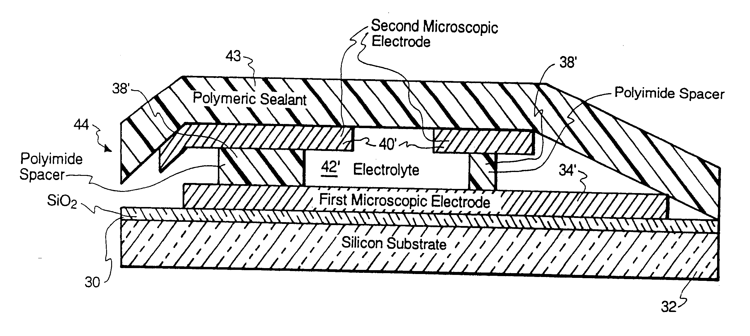
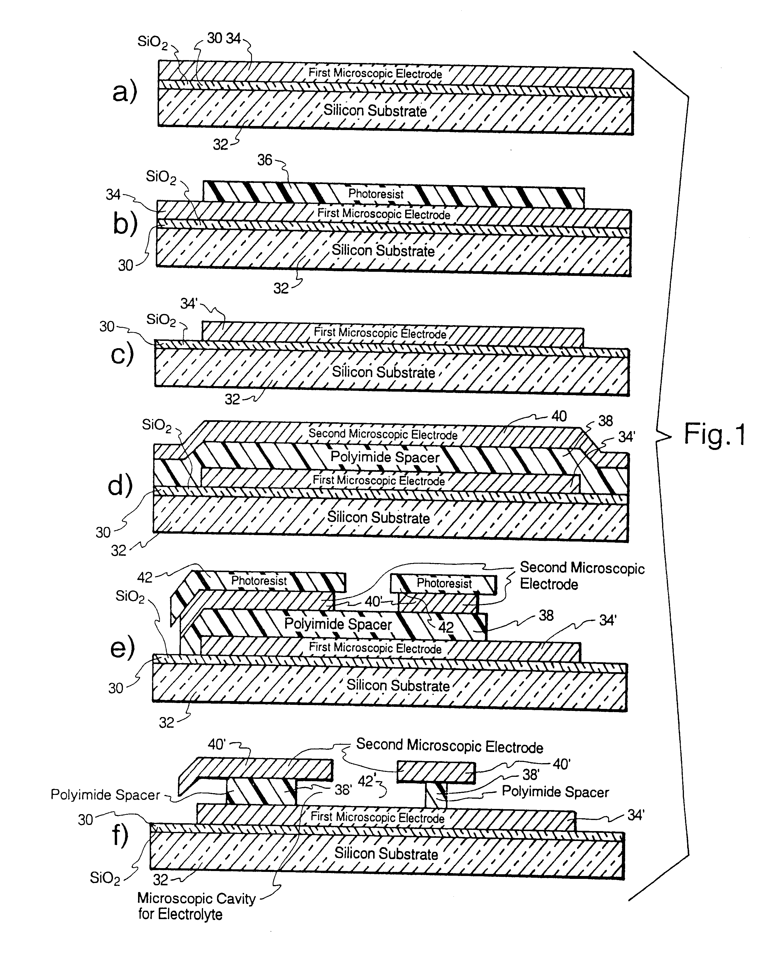
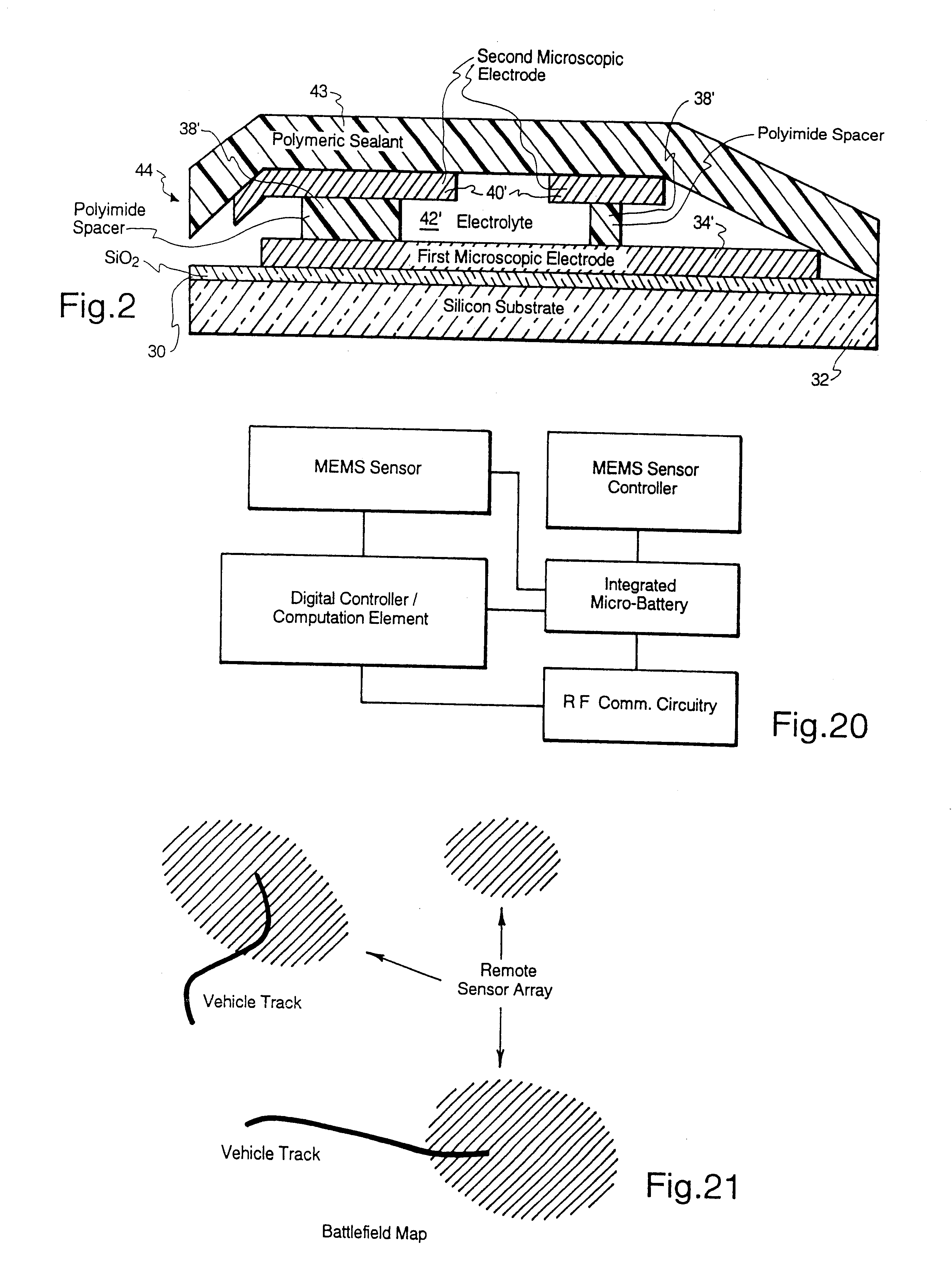
Microscopic batteries of the invention are adapted to be located internally within a MEMS or other microcircuitry, in close proximity to the requirements for power. During periods of high energy usage, high specific power is immediately available from the fully integrated internal microscopic battery, without significant power loss. In typical applications, the battery can be recharged from an external source at a lower rate, thus reducing power transmission losses although recharging is not normally required at frequent intervals. The battery serves as a load-leveling energy storage device. Thus, features of importance of the microbatteries of the invention are reduced power loss when integrated into a MEMS or like microscopic system, higher energy efficiency, remotely controlled microscopic robotics, and mobility via the autonomy of the system. The invention also embraces novel methods of microfabrication of microscopic batteries including unitary fabrication of the microscopic battery as an integrated part of an autonomous integrated circuit, such as MEMS. Such circuits, therefore, are complete with an internal microscopic source of electrical energy and can operate without any external power supply or connections thereto.
The above-described micro fabrication steps lend themselves well to mass production, which produces low costs of manufacture and low rejection rates.

Problems solved by technology

As mentioned above, one of the limiting factors in the operation of MEMS has been energy transmission and storage.
In conventional practice, electrical energy for a MEMS is supplied from an external source into the microcircuit, which causes substantial power losses.

Method used


Image

  • Microscopic batteries for MEMS systems
  • Microscopic batteries for MEMS systems
  • Microscopic batteries for MEMS systems

Examples


example ii

Fabrication of a Metal-Hydride / Nickel Hydroxide Microscopic Battery with Liquid Electrolyte

A microbattery was constructed, essentially as in Example I, except that the anode comprised a metal hydride instead of zinc metal. For the metal-hydride anode electrodes, a two component hydride of lanthanum / nickel alloy was used. This electrode was constructed in the discharged state (i.e., not loaded with hydrogen). Thin films of La--Ni were formed by evaporating from a La--Ni melt. The composition and temperature of the La--Ni melt was carefully controlled. Also, the metal was alloyed after deposition to ensure that the hydride had the best structure for hydrogen insertion.

example iii

Fabrication of Zinc / Nickel Hydroxide Microscopic Battery with Liquid Electrolyte in Porous Spacer

A zinc / nickel hydroxide microbattery was constructed. The cathode is formed essentially as in Example I by forming an oxide layer and thereafter a NiOOH cathode. After patterning of the cathode, a layer of porous material for the electrolyte is formed.

example iv

Fabrication of Solid Electrolyte Microscopic Battery

Microscopic batteries with a solid-state electrolyte were made. Despite their lower power performance relative to liquid electrolyte batteries, solid electrolyte batteries are attractive for applications which require, for example, batteries to bend or conform to a particular shape, or to operate over a broad range of temperatures.

Two different solid electrolyte materials were used, i.e. tetramethylammonium hydroxide pentahydrate (TMAOH) and polyethylene oxide / potassium hydroxide (PEO / KOH). TMAOH is a solid electrolyte material used heretofore in a solid-state Ni / MH battery which can provide current densities of 10 mA / cm.sup.2 PEO, widely used in solid state cells, is a polymer to which a salt can be added to produce a finite ionic conductivity.


PUM

PropertyMeasurementUnit
areaaaaaaaaaaa
specific energyaaaaaaaaaa

Abstract

Microscopic batteries, integratable or integrated with microelectromechanical systems or other microscopic circuits, including a MEMS microcircuit, and methods of microfabrication of such microscopic batteries are disclosed, among which comprise closed system microscopic batteries for internal storage of electricity using interval reactants only, which comprise microscopic electrodes, electrolyte and reservoir for the electrolyte.

Description

This invention relates generally to electrical power sources and more particularly to microscopic batteries some forms of which are integrated or integratable with and providing internal power to MEMS and integrated microcircuits, either on a retrofit or original manufacture basis. MEMS (microelectromechanical systems) involve the fabrication and use of miniature devices which comprise microscopic moving parts (such as motors, relays, pumps, sensors, accelerometers, etc.). MEMS devices can be combined with integrated circuits, and can perform numerous functions.Integrated circuits, including microelectronic circuits, have been used extensively, and have the advantage of small size and low production costs particularly when produced on a large scale. A class of integrated circuits that are of particular interest comprise microelectronic circuits having at least one MEMS device. MEMS may comprise complex engineering systems comprising microscopic mechanical elements, such as motors, p...

Claims


Application Information

Patent Timeline
Patent Type & Authority Patents(United States)
IPC IPC(8): H01M6/04H01M10/00H01M2/08H01M6/00H01M6/10H01M6/12H01M6/42H01M6/46H01M10/04H01M10/28H01M10/42H01M14/00H01M50/11H02J7/00H02K37/24
CPCH01M2/0202H01M10/0436H01M10/287H01M10/30H01M10/42H01M10/425H01M10/342H01M6/40Y10T29/49108Y02E60/124Y10T29/49115H01L2224/48091Y02E60/10Y02P70/50H01M50/11H01L2924/00014
Inventor LAFOLLETTE, RODNEY M.SALMON, LINTON G.HARB, JOHN N.
Owner BIPOLAR TECH
Why Eureka
Try Eureka