Chemical vapor deposition method using a catalyst on a substrate surface

a chemical vapor deposition and substrate technology, applied in the direction of physical/chemical process catalysts, organic compounds/hydrides/coordination complex catalysts, coatings, etc., can solve the problems of reducing the surface reaction rate, increasing the process time, and difficult to obtain a film of uniform thickness, etc., to achieve a high surface reaction rate and high deposition rate without adversely affecting the step coverage

Inactive Publication Date: 2003-09-23
ASM KOREA LTD
View PDF4 Cites 127 Cited by
  • Summary
  • Abstract
  • Description
  • Claims
  • Application Information

AI Technical Summary

Benefits of technology

Accordingly, it is an object of the present invention to provide a method of chemically depositing a film a...

Problems solved by technology

However, this can be achieved only when the film formation is controlled by surface reactions.
If the formation of a film is controlled by vapor phase reaction or mass transport rate at which the deposition sources travel to the substrate surface, although chemical deposition is utilized, it is difficult to obtain a film of uniform thickness.
However, the lowered surface reaction rate could increase the ...

Method used


Image

  • Chemical vapor deposition method using a catalyst on a substrate surface
  • Chemical vapor deposition method using a catalyst on a substrate surface
  • Chemical vapor deposition method using a catalyst on a substrate surface

Examples


exemplary embodiment 1

The copper film was formed in the same manner as described in the comparative example 1, except that the supply of copper source was stopped during the deposition of copper film while iodoethane was introduced into the reactor. The residual iodoethane in the reactor was removed by injecting argon gas therein at a flow rate of 20 sccm. Thereafter, only copper source was continuously supplied into the reactor by an argon carrier gas, forming a copper film up to 1 .mu.m thick.

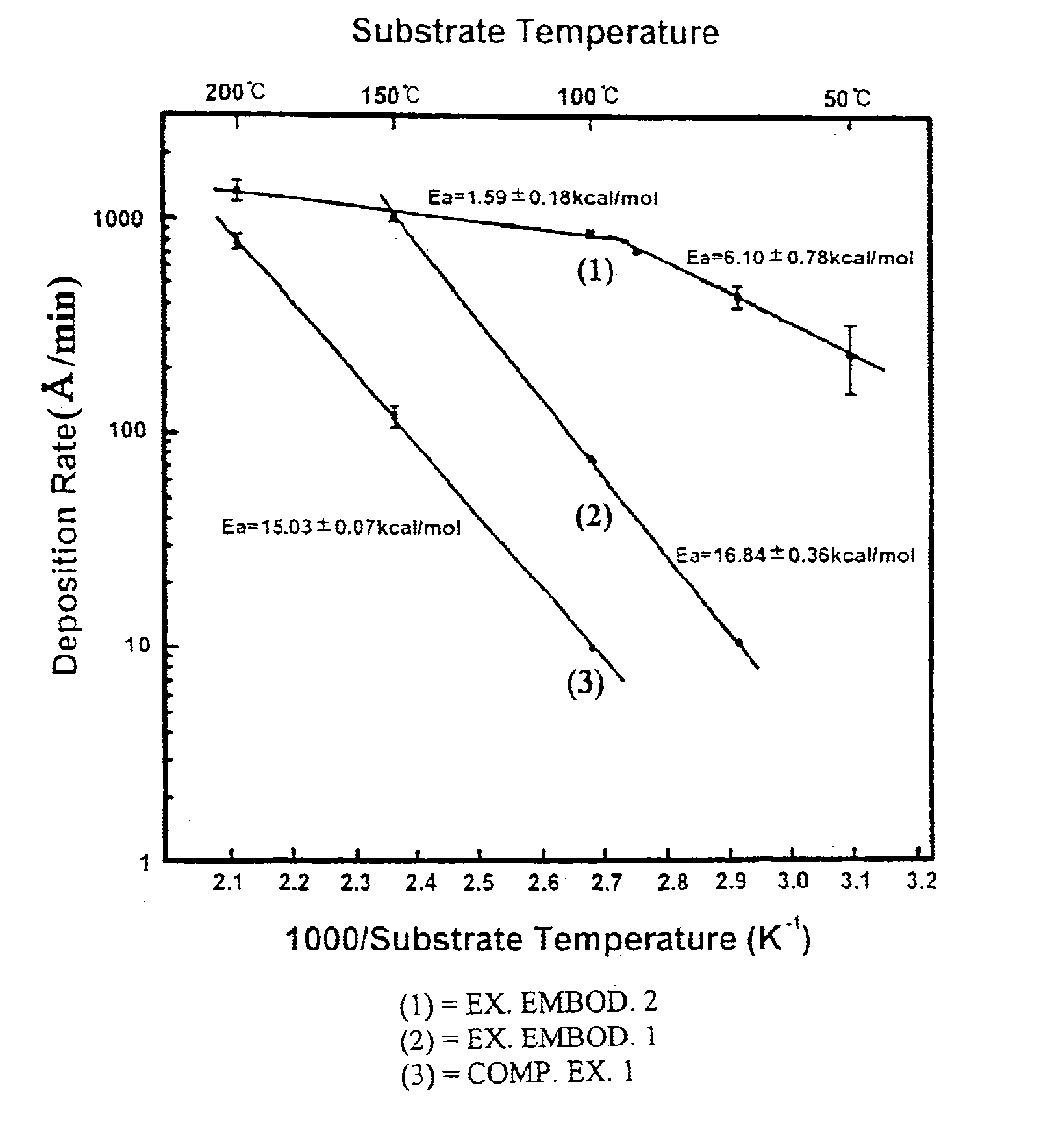
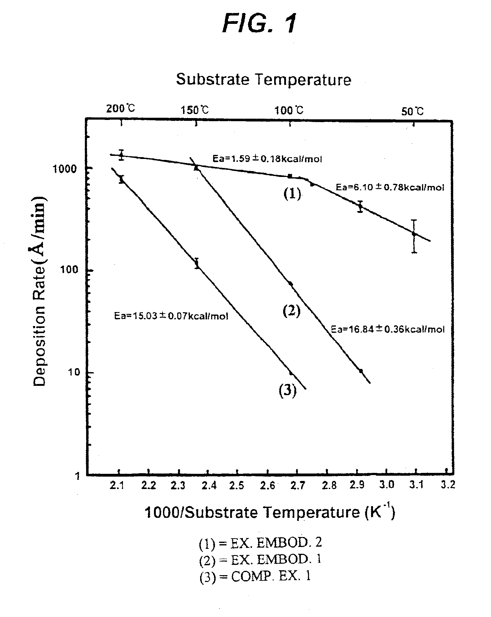
The deposition rate of copper film at each substrate temperature is shown by a solid line (2) in FIG. 1. Referring to FIG. 1, it will be understood that the deposition rate of exemplary embodiment 1 is 7-10 times higher than that of comparative example 1 under a same temperature condition.

The observed increase in deposition rate can be interpreted to be caused by the contribution of a catalyst component to the decomposition of copper source, the catalyst component being generated from the decomposition of iodoetha...

exemplary embodiment 2

The copper film was formed in the same manner as described in the comparative example 1 except that the copper source was supplied at a 60 mTorr iodoethane partial pressure. The deposition rate of copper film at each substrate temperature is shown by a solid line (1) in FIG. 1. It is found that the deposition rate of exemplary embodiment 2 is about 100 times higher than that of comparative example 1 at a substrate temperature of 100.degree. C. In the case of supplying only copper source no copper film was formed at a relatively low temperature of 50.degree. C., but in the exemplary embodiment 2 a deposition rate of 250 .ANG. / min was achieved even at such a low temperature.

In the exemplary embodiments 1 and 2, the resistivity of a copper film formed at a temperature in the range of 50 to 200.degree. C. was 2.01.+-.0.13 .mu..OMEGA..multidot.cm, which is comparable to the resistivity 1.7 .mu..OMEGA..multidot.cm of pure copper. Moreover, the copper thin film chemically deposited at a su...

exemplary embodiment 3

The process conditions were the same as the exemplary embodiment 2, except that the film was deposited at various iodoethane partial pressures and at a temperature of 100.degree. C. FIG. 7 is a graphical depiction of copper film deposition rate versus partial pressure of iodoethane. Referring to FIG. 7, it is found that the partial pressure of iodoethane has little effect on the deposition rate at a partial pressure in the range of 5 to 60 mTorr.


PUM

PropertyMeasurementUnit
Deposition rateaaaaaaaaaa

Abstract

A method of chemically depositing a copper film in which a bromine or iodine-containing catalyst component is employed to enhance the deposition rate. The present invention is characterized in that the catalyst component floats on the film surface during the film formation. Accordingly, a film deposition having superior step coverage and high deposition rate is obtained.

Description

The present invention relates to a chemical deposition method, and more particularly, to a method of chemically depositing a film in which a catalyst component is employed to enhance the deposition rate.As the overall dimensions of semiconductor devices continue to shrink, the demand is ever increasing to form a film of a uniform thickness despite the unevenness of substrate surface. For example, it should be accomplished in the manufacture of semiconductor devices to fill a contact hole with a diameter of about 100 nm and an aspect ratio of 10. Chemical deposition method has an advantage of forming a film of a relatively uniform thickness on an uneven substrate surface. However, this can be achieved only when the film formation is controlled by surface reactions. If the formation of a film is controlled by vapor phase reaction or mass transport rate at which the deposition sources travel to the substrate surface, although chemical deposition is utilized, it is difficult to obtain a...

Claims


Application Information

Patent Timeline
IPC IPC(8): C23C16/18C23C16/44C23C16/14B01J31/02H01L21/74
CPCC23C16/18C23C16/44H01L21/74
Inventor LEE, JI-HWAHWANG, EUI-SEONG
Owner ASM KOREA LTD
Why Eureka
Try Eureka