Laser wavelength control unit with piezoelectric driver

a technology of piezoelectric driver and laser, which is applied in the direction of instruments, photomechanical equipment, active medium materials, etc., can solve the problems of insufficient correction of large and sudden wavelength shifts, insufficient prior art wavelength correction techniques, and insufficient correction of small very rapidly occurring (high frequency) wavelength shifts

Inactive Publication Date: 2003-11-18
CYMER INC
View PDF7 Cites 31 Cited by
  • Summary
  • Abstract
  • Description
  • Claims
  • Application Information

AI Technical Summary

Problems solved by technology

The etalon creates an interference pattern having concentric bands of dark and light levels due to destructive and constructive interference by the laser light.
However, they have not been very effective in controlling wavelengths over short time periods of about 3 to 30 milliseconds or very short time periods of about 1-3 milliseconds or le...

Method used


Image

  • Laser wavelength control unit with piezoelectric driver
  • Laser wavelength control unit with piezoelectric driver
  • Laser wavelength control unit with piezoelectric driver

Examples


Embodiment Construction

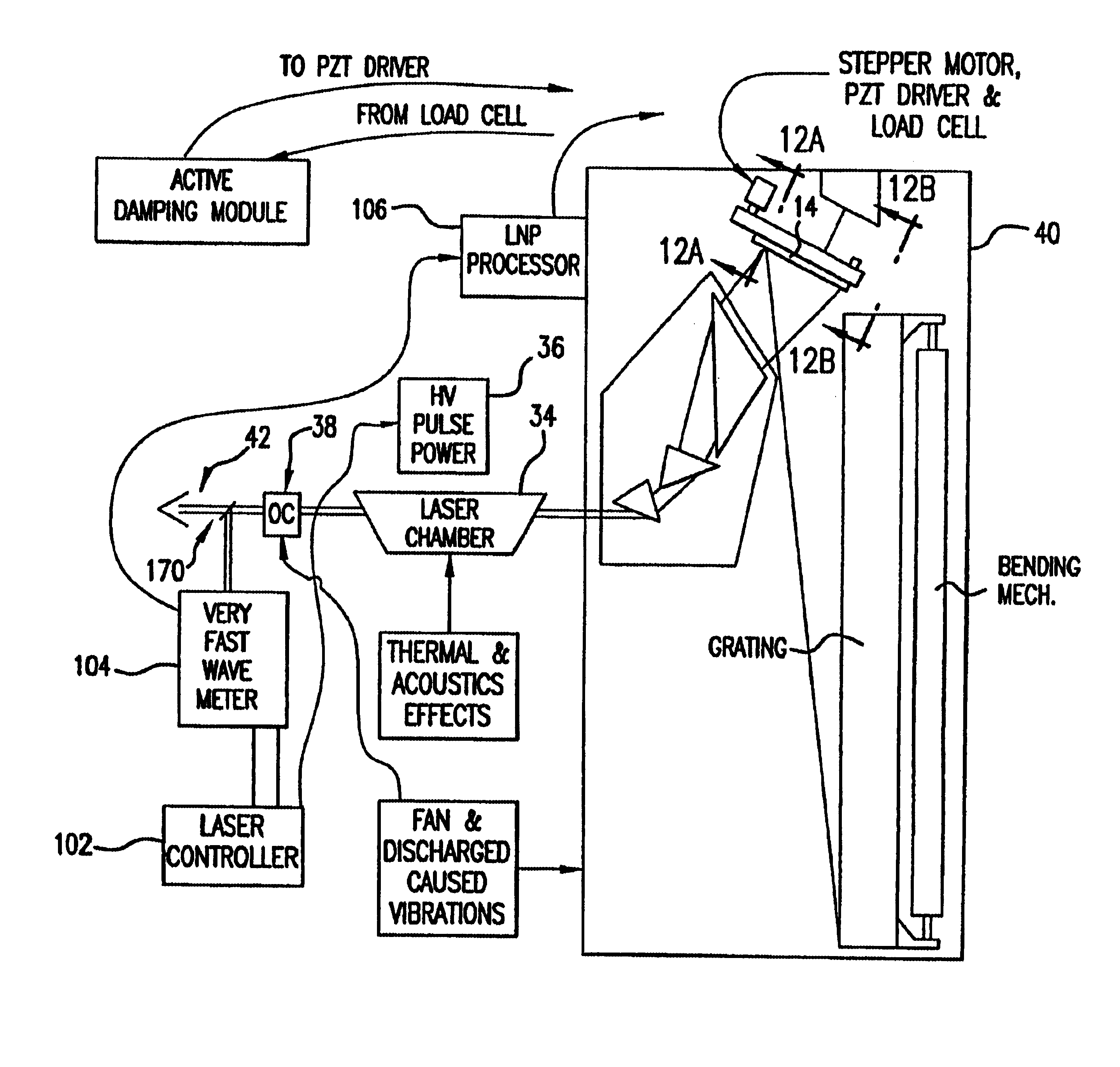
Important features of a first preferred embodiment of the present invention are shown in FIG. 4. This embodiment shows a KrF excimer laser system useful as a light source for integrated circuit fabrication. The system includes laser chamber 34 which contains a laser gas circulated with a motor driven fan (not shown) between two elongated electrodes (not shown) between which electric discharges are produced at rates of up to 4,000 Hz by a pulse power system 36 controlled by laser controller 102. A resonant cavity defined by output coupler 38 and LNP 40 produces laser beam 42. A portion of laser beam 42 is monitored by very fast wavemeter 104 which provides pulse energy measurements to laser controller 102 for feedback control of the pulse power unit 36 for maintaining pulse power within desired limits. Wavemeter 104 also measures the center-line wavelength of the laser beam and provides a feedback signal to LNP processor which uses the feedback signal to control a stepper motor 82 an...


PUM


Abstract

An electric discharge laser with fast wavelength correction. Fast wavelength correction equipment includes at least one piezoelectric drive and a fast wavelength measurement system and fast feedback response times. In a preferred embodiment, equipment is provided to control wavelength on a slow time frame of several milliseconds, on a intermediate time from of about one to five milliseconds and on a very fast time frame of a few microseconds. Preferred techniques include a combination of a relatively slow stepper motor and a very fast piezoelectric driver for tuning the laser wavelength using a tuning mirror. A preferred control technique is described (utilizing a very fast wavelength monitor) to provide the slow and intermediate wavelength control with the combination of a stepper motor and a piezoelectric driver. Very fast wavelength control is provided with a piezoelectric load cell in combination with the piezoelectric driver. Preferred embodiments provide (1) fast feedback control based on wavelength measurements, (2) fast vibration control, (3) active damping using the load cell and an active damping module, (4) transient inversion using feed forward algorithms based on historical burst data. A preferred embodiment adapts the feed forward algorithms to current conditions. Another preferred embodiment measures tuning mirror position to permit wavelength pretuning and active wavelength tuning.

Description

Background of the InventionLight Sources For Integrated Circuit FabricationAn important use of gas discharge excimer lasers is to provide high quality light sources for integrated circuit fabrication. These light sources are used by stepper machines and scanner machines for selectively exposing photoresist in a semiconductor wafer fabrication process. In such fabrication processes, the optics in the stepper and scanner machines are designed for a particular laser beam with a narrow band of wavelengths. The output beam of the excimer laser is typically comprised of a very narrow band of wavelengths distributed about a "central" wavelength (referred to as the "line center" wavelength) approximately in a gausian distribution. For krypton fluoride (KrF) and argon fluoride (ArF) excimer lasers the output beam is "line narrowed" to produce the desired narrow band of wavelengths. The laser center line wavelength may drift over time and, thus, a feedback network is typically employed to det...

Claims


Application Information

Patent Timeline
IPC IPC(8): G03F7/20H01S3/14H01S3/036H01S3/104H01S3/225H01S3/038H01S3/1055H01S3/134H01S3/131H01S3/04H01S3/11H01S3/097H01S3/0971H01S3/137H01S3/22H01S3/105H01S3/041H01S3/0975H01S3/13H01L21/027H01S3/00H01S3/10H01S3/101H01S3/139
CPCG03F7/70025H01S3/225G03F7/70333G03F7/70575G03F7/70933H01S3/036H01S3/0385H01S3/104G03F7/70041H01S3/02H01S3/038H01S3/0404H01S3/041H01S3/08036H01S3/097H01S3/0971H01S3/0975H01S3/105H01S3/1055H01S3/1305H01S3/1312H01S3/134H01S3/137H01S3/22H01S3/2207H01S3/10
Inventor SPANGLER, RONALD L.JACQUES, ROBERT N.RULE, JOHN A.PALENSCHAT, FREDERICK A.FOMENKOV, IGOR V.ALGOTS, JOHN M.LIPCON, JACOB P.SANDSTROM, RICHARD L.
Owner CYMER INC
Why Eureka
Try Eureka